This thread has been locked.

If you have a related question, please click the "Ask a related question" button in the top right corner. The newly created question will be automatically linked to this question.

CCS/MSP-EXP430F5529LP: GUI Composer v2 not working

Part Number: MSP-EXP430F5529LP
Other Parts Discussed in Thread: BQ76PL536EVM-3, ENERGIA

Tool/software: Code Composer Studio

Hello Forum

I am trying to use GUI Composer v2 to create a GUI for the SLAA478 Battery Management System Application using the MSP-EXP430F5529LP and bq76PL536EVM-3. I have verified that the code works in CCS v7. Variables are being read by the LaunchPad, but I no data is being sent to the host PC. 

On CCS Cloud, the code does not appear function correctly, as not all cell voltages are being read correctly (seen in debug mode). Additionally, any action run/debug in CCS Cloud gives the message "Unknown breakpoint id: 117." I have removed all breakpoints from the code, so I am not sure what this means.

When I try using GUI Composer v2, I select USB/Serial IO for target communications, then click "Connect" to connect to COM3 at a baud rate of 57600. These are the correct settings for the COM port the LaunchPad is connected to.

I place components in the GUI, and link them to variables in the program, using the chainlink next to the 'value' field, after selecting 'target_device'. I run the GUI (both with the program on the LaunchPad running, and not running), and nothing happens in the GUI. No data is being shown.

I tried using the XDS Debug Port/Target Monitor setting, but was prompted to upload a 'Target Executable' file, and I am unsure what this is. In fact, the only file uploaded, was the entire project folder, to CCS Cloud.

I have searched the forums and the wider web, looking for answers, but proper documentation on GUI Composer v2 seems scarce/non-existent. I tried reverting back to CCS v6, but the program I am running is too large for CCS v6 to program the LaunchPad.

Has anyone else experienced this problem? Can anyone assist me in sorting this out?

Is it possible to build a GUI to just display the values of variables storedon the LaunchPad, and not sent to the host PC via the Serial port?

Should I be connected to CCS Cloud before using GUI Composer v2, or not? Does the program need to be running prior to selecting 'Run' in GUI Composer v2?

Regards

  • Does no one have any possible solutions?
  • HI Raheem, 

    The Users Guide has some information on interactions with target. Direct link below. 

    5529(all MSP430 devices) has some limitations in that when the cpu is running debug accesses can not be made. i.e. you have to halt the CPU before you can see variables in expression view. At least that is the default behaviour, there is a way of configuring CCS Desktop to force a halt, update views and then run the CPU. However, during refresh the CPU is halted thus your application is not running. 

    USB/Serial IO communication mode works only when your 5529 CPU has code that can send/encode data to be displayed in JSON format. Depending on your use case this may work for you, but you would need to change the program running on 5529 CPU. 

    XDS / Target Monitor: For some devices debug probe can access devices memory without any special changes to the program. Unfortunately, MSP430 does not have this support, thus it requires a target monitor. Target monitor (at least the target side of things is the same as for  GCv1 which is documented below). In essence you need to add to your program that runs on 5520 the same implementation that handles memory read/writes. 

    Both of above options can be made to work with 5529, however, both require you to change the target program (i.e. the output of CCS project when you hit build, usually has .out extension). Either to send JSON strings with encoded data or target monitor that can provide read/write memory service. 

    martin

  • Hello Martin

    Thanks for your response, and those links. I have decided it may be best for me to go the USB/Serial IO route, using JSON.

    I am starting with the BlinkJsonUart tutorial project, and have verified that it works. The code made available from this project is:

    #include <aJSON.h>
    
    // most launchpads have a red LED
    #define LED RED_LED
    
    //see pins_energia.h for more LED definitions
    void printled_statewithjson(int state){
      aJsonObject* root = aJson.createObject();
      if (root == NULL) {
        return;
      }
    
      aJson.addItemToObject(root, "LED", aJson.createItem(state));
    
      char* string = aJson.print(root);
      
      if (string != NULL) {
        Serial.println(string);
        free(string);
      } 
      
      aJson.deleteItem(root);
    }
      
    // the setup routine runs once when you press reset:
    void setup() {                
      // initialize the digital pin as an output.
      pinMode(LED, OUTPUT);     
      Serial.begin(9600); 
    }
    
    // the loop routine runs over and over again forever:
    void loop() {
      digitalWrite(LED, HIGH);   // turn the LED on (HIGH is the voltage level)
      printled_statewithjson(1); // print json object with LED status set to 1 to UART
      delay(1000);               // wait for a second
      digitalWrite(LED, LOW);    // turn the LED off by making the voltage LOW
      printled_statewithjson(0); // print json object with LED status set to 0 to UART
      delay(1000);               // wait for a second
    }

    Of the 3 functions, I understand what the loop() and setup() functions do. But I do not fully understand how printled_statewithjson() [line 19] works. Based on the information sent through the COM Port, I can tell that line 25 contains the information to be sent. Though I'm unsure of what exactly the "root" variable does, "LED" here must be referring to the name of the widget in the GUI, and "aJson.createItem(state)" must be telling the GUI whether the LED is on or off (1 or 0). Is this correct?

    Finally, to implement similar code in my program, I am thinking that the necessary steps are to include the "aJSON.h" and "energia.h" headers, then use a function similar to printled_statewithjson().


    Regards

  • Hi Raheem,

     printled_statewithjson function is using aJson energia library. If you read documentation for it, it should become clearer how that function works. here is a link to github that has that library and some documentation for it. 

    Using that library is probably useful when you need to send complex JSON objects. However, if you just want to send few simple variables then it might be simpler to just print to serial. below is a simple example that pretty much does the same thing. i.e. it sends 

    {"led":"0"}

    or 

    {"led":"1"} 

    strings over serial port depending on whether blink example turns LED on or off. 

    _____________________________

    // most launchpads have a red LED

    #define LED RED_LED

    volatile unsigned int blinkCounter;


    //see pins_energia.h for more LED definitions

    //#define LED GREEN_LED


    // the setup routine runs once when you press reset:

    void setup() {               

      // initialize the digital pin as an output.

      pinMode(LED, OUTPUT);    

        //Initialize serial and wait for port to open:

      Serial.begin(9600);

    }


    // the loop routine runs over and over again forever:

    void loop() {

      digitalWrite(LED, HIGH);   // turn the LED on (HIGH is the voltage level)

      delay(1000);               // wait for a second

      Serial.println("{\"led\":1\}");

      blinkCounter++;

      digitalWrite(LED, LOW);    // turn the LED off by making the voltage LOW

      delay(1000);               // wait for a second

      Serial.println("{\"led\":0\}");

      blinkCounter++;

    }

  • Okay then, thanks.

    The Serial.print() method is easier, but does CCS v7come with the library installed to use it? How about CCS Cloud?

    From the reseach I did, it seems that the library comes with Energia, which I am not using. I tried including the "aJSON.h" and "energia.h" libraries in CCS v7, but errors are always occuring, stating that more header files/libraries need to be included.

    Regards

  • Martin,

    I went ahead and tried to print to serial using different functions I found in use in the program. This is my snippet of code:

    if (g%2 == 0){
           strcpy(OutputString,"{\"LED\":0\}");
           #ifdef UART_COMM
           // Send the message to the host over UART
                 putsUART((BYTE*)OutputString,strlen(OutputString));
           #endif
       }
       else{
           strcpy(OutputString,"{\"LED\":1\}");
           #ifdef UART_COMM
           // Send the message to the host over UART
                 putsUART((BYTE*)OutputString,strlen(OutputString));
           #endif
       }
       g++;

    The code should be alternately sending {"led":"0"} or {"led":"1"}. I confirmed that this works, using PuTTY:

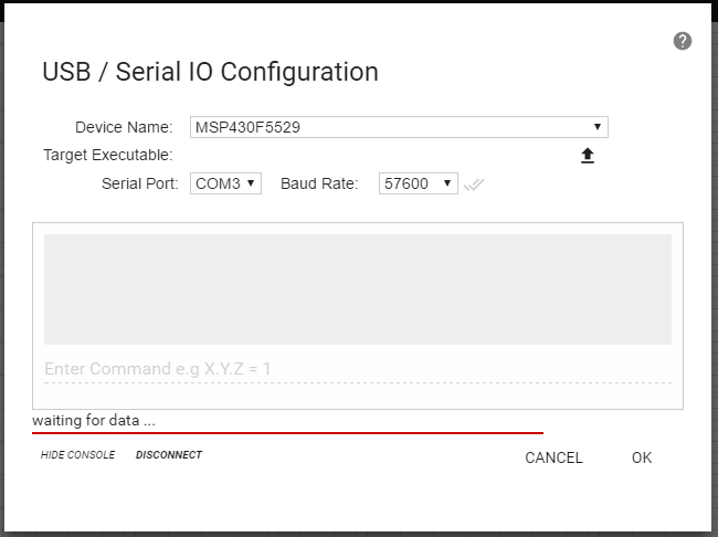
    But when I try connecting to the device via GUI Composer v2, the service either does not connect, or does not receive the data. This is what I am seeing:

    And that red bar at the bottom continues on forever; no data ever shows in the console.

    Do you know how to fix this?

    Regards

  • Hi Raheem, 

    Looking at putty picture that you attached, both name and value need to be quoted. i.e. it should be {"LED":"0"} Putty is showing {"LED":0}

    Martin

  • Hello Martin

    That was my mistake. I have adjusted the code so that the output is {"LED":"0"}, and GUI Composer v2 recognizes the data now. Thanks for the help.

    Regards