This thread has been locked.

If you have a related question, please click the "Ask a related question" button in the top right corner. The newly created question will be automatically linked to this question.

CCS/TMS320F28069M: you require a target configuration to start a debug session

Part Number: TMS320F28069M

Tool/software: Code Composer Studio

When I debug the example program, it will show 'you require a target configuration to start a debug session'. In fact I have debugged the program, why does it say in this way? Can anybody tell me why?

  • I make a small change to my sentence. It is that 'In fact, I have done the target configuration'.
  • Do you have a .ccxml inside your project? This file contains the target configuration. If there is one in the project they it will get used automatically when launching a debug session. If there is not one in the project then CCS checks if one has been setup as a default and will use it.

    If you go to the view menu and open the Target Configurations view, it will let you setup a default target configuration. To set a target configuration as the default, right click on it and select set as default.

    Regards,
    John
  • Dear John

    Thanks for your response first. I have found the target configuration and done it. However, a new issue comes, which is

    'Error connecting to the target:

    (Error -1135 @ 0x0)

    The debug probe reported an error. Confirm debug probe configuration and connections, reset the debug probe, and retry the operation.

    (Emulation package 6.0.576.0)'

    and in the target configuration, when I do the test connection, it says

    '[Start: Texas Instruments XDS100v2 USB Debug Probe_0]

    Execute the command:

    %ccs_base%/common/uscif/dbgjtag -f %boarddatafile% -rv -o -F inform,logfile=yes -S pathlength -S integrity

    [Result]

    -----[Print the board config pathname(s)]------------------------------------

    C:\Users\ADMINI~1\AppData\Local\TEXASI~1\

       CCS\CCS_71~1.000\0\0\BrdDat\testBoard.dat

    -----[Print the reset-command software log-file]-----------------------------

    This utility has selected a 100- or 510-class product.

    This utility will load the adapter 'jioserdesusb.dll'.

    The library build date was 'Feb 13 2017'.

    The library build time was '16:06:25'.

    The library package version is '6.0.576.0'.

    The library component version is '35.35.0.0'.

    The controller does not use a programmable FPGA.

    The controller has a version number of '4' (0x00000004).

    The controller has an insertion length of '0' (0x00000000).

    This utility will attempt to reset the controller.

    This utility has successfully reset the controller.

    -----[Print the reset-command hardware log-file]-----------------------------

    The scan-path will be reset by toggling the JTAG TRST signal.

    The controller is the FTDI FT2232 with USB interface.

    The link from controller to target is direct (without cable).

    The software is configured for FTDI FT2232 features.

    The controller cannot monitor the value on the EMU[0] pin.

    The controller cannot monitor the value on the EMU[1] pin.

    The controller cannot control the timing on output pins.

    The controller cannot control the timing on input pins.

    The scan-path link-delay has been set to exactly '0' (0x0000).

    -----[The log-file for the JTAG TCLK output generated from the PLL]----------

    There is no hardware for programming the JTAG TCLK frequency.

    -----[Measure the source and frequency of the final JTAG TCLKR input]--------

    There is no hardware for measuring the JTAG TCLK frequency.

    -----[Perform the standard path-length test on the JTAG IR and DR]-----------

    This path-length test uses blocks of 64 32-bit words.

    The test for the JTAG IR instruction path-length failed.

    The JTAG IR instruction scan-path is stuck-at-ones.

    The test for the JTAG DR bypass path-length failed.

    The JTAG DR bypass scan-path is stuck-at-ones.

    -----[Perform the Integrity scan-test on the JTAG IR]------------------------

    This test will use blocks of 64 32-bit words.

    This test will be applied just once.

    Do a test using 0xFFFFFFFF.

    Scan tests: 1, skipped: 0, failed: 0

    Do a test using 0x00000000.

    Test 2 Word 0: scanned out 0x00000000 and scanned in 0xFFFFFFFF.

    Test 2 Word 1: scanned out 0x00000000 and scanned in 0xFFFFFFFF.

    Test 2 Word 2: scanned out 0x00000000 and scanned in 0xFFFFFFFF.

    Test 2 Word 3: scanned out 0x00000000 and scanned in 0xFFFFFFFF.

    Test 2 Word 4: scanned out 0x00000000 and scanned in 0xFFFFFFFF.

    Test 2 Word 5: scanned out 0x00000000 and scanned in 0xFFFFFFFF.

    Test 2 Word 6: scanned out 0x00000000 and scanned in 0xFFFFFFFF.

    Test 2 Word 7: scanned out 0x00000000 and scanned in 0xFFFFFFFF.

    The details of the first 8 errors have been provided.

    The utility will now report only the count of failed tests.

    Scan tests: 2, skipped: 0, failed: 1

    Do a test using 0xFE03E0E2.

    Scan tests: 3, skipped: 0, failed: 2

    Do a test using 0x01FC1F1D.

    Scan tests: 4, skipped: 0, failed: 3

    Do a test using 0x5533CCAA.

    Scan tests: 5, skipped: 0, failed: 4

    Do a test using 0xAACC3355.

    Scan tests: 6, skipped: 0, failed: 5

    Some of the values were corrupted - 83.3 percent.

    The JTAG IR Integrity scan-test has failed.

    -----[Perform the Integrity scan-test on the JTAG DR]------------------------

    This test will use blocks of 64 32-bit words.

    This test will be applied just once.

    Do a test using 0xFFFFFFFF.

    Scan tests: 1, skipped: 0, failed: 0

    Do a test using 0x00000000.

    Test 2 Word 0: scanned out 0x00000000 and scanned in 0xFFFFFFFF.

    Test 2 Word 1: scanned out 0x00000000 and scanned in 0xFFFFFFFF.

    Test 2 Word 2: scanned out 0x00000000 and scanned in 0xFFFFFFFF.

    Test 2 Word 3: scanned out 0x00000000 and scanned in 0xFFFFFFFF.

    Test 2 Word 4: scanned out 0x00000000 and scanned in 0xFFFFFFFF.

    Test 2 Word 5: scanned out 0x00000000 and scanned in 0xFFFFFFFF.

    Test 2 Word 6: scanned out 0x00000000 and scanned in 0xFFFFFFFF.

    Test 2 Word 7: scanned out 0x00000000 and scanned in 0xFFFFFFFF.

    The details of the first 8 errors have been provided.

    The utility will now report only the count of failed tests.

    Scan tests: 2, skipped: 0, failed: 1

    Do a test using 0xFE03E0E2.

    Scan tests: 3, skipped: 0, failed: 2

    Do a test using 0x01FC1F1D.

    Scan tests: 4, skipped: 0, failed: 3

    Do a test using 0x5533CCAA.

    Scan tests: 5, skipped: 0, failed: 4

    Do a test using 0xAACC3355.

    Scan tests: 6, skipped: 0, failed: 5

    Some of the values were corrupted - 83.3 percent.

    The JTAG DR Integrity scan-test has failed.

    [End: Texas Instruments XDS100v2 USB Debug Probe_0]'

    I do not know whether it is correct and in my device manager, it shows as following:

    I know I am missing the TI XDS 100 Channel A and TI XDS 100 Channel B in Universal Serial Bus controllers. However, I have reinstalled the software and tried again, it still did not show these two items and I also check whether there are some XDS 100 drivers on the internet, I found there is not any XDS 100 driver separately. On the internet, it says the XDS 100 driver is together with code composer studio, so it means when I install the CCS, the driver should have been installed. Therefore, do you know where my fault is and how to solve? Thanks a lot and look forward to your response.

    Kind regards

    Shaochuan Zhang

  • Looks like the drivers are installed ok. Are you using a F28069M LaunchPad? Can you send a screen shot of your .ccxml or attach it.
  • Shaochuan Zhang said:
    Therefore, do you know where my fault is and how to solve?

    Those errors from the test connection can occur if the boot mode of the TMS320F28069M is not set to "emulation boot mode".

    I don't which board you are using, and how to select the boot mode is board specific.

    See XDS100v2 USB Debug Probe Failed 'Test Connection' on LAUNCHXL-F28069M for the F28069M launchpad.

  • Dear John

    Yes, I am using a F28069M LaunchPad. That is my screen shot of .ccxml

  • Dear Chester

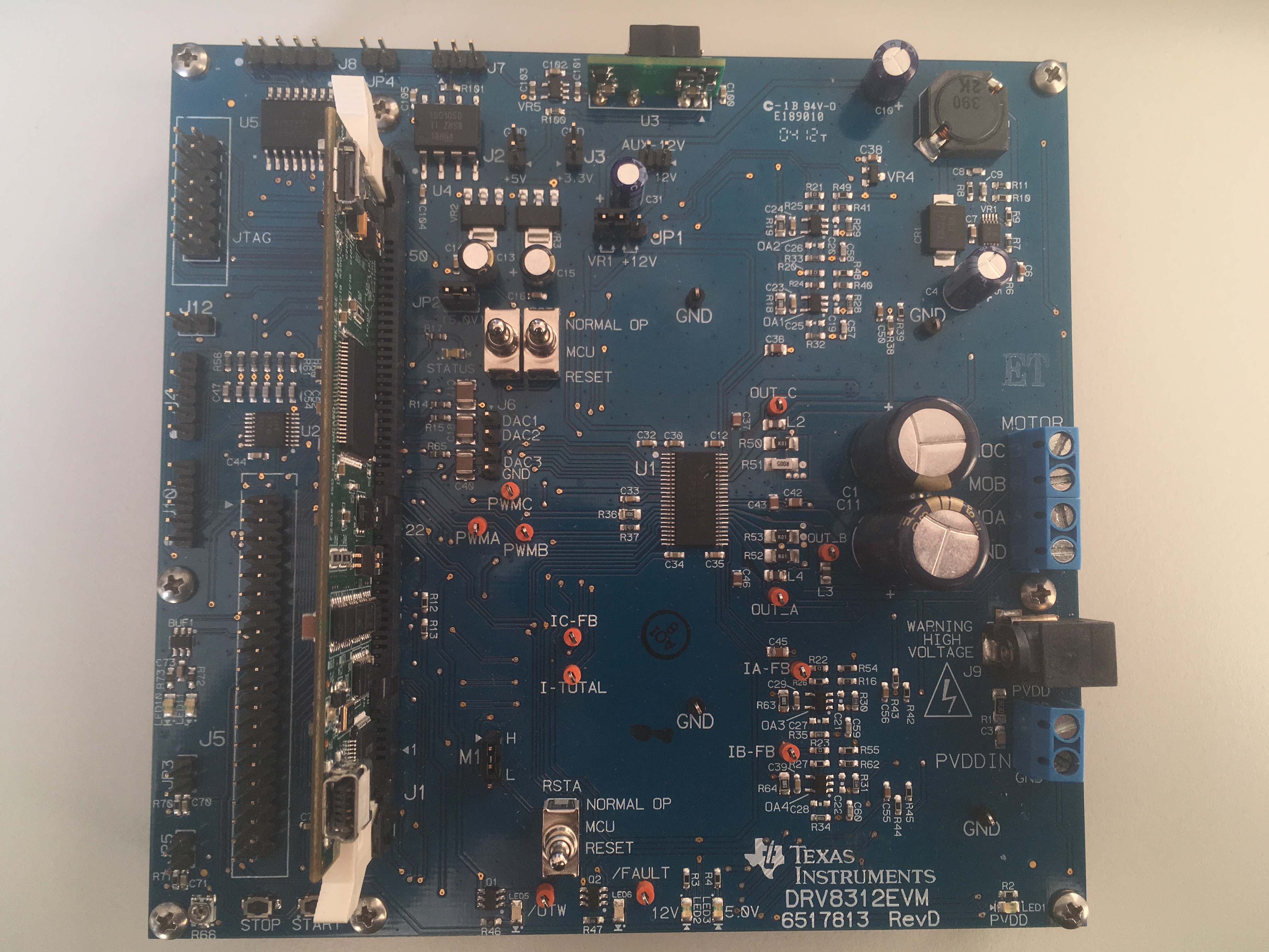
    The board that I am using is DRV8312EVM and the microcontroller is TMS320F28069M

    Kind regards

    Shaochuan Zhang

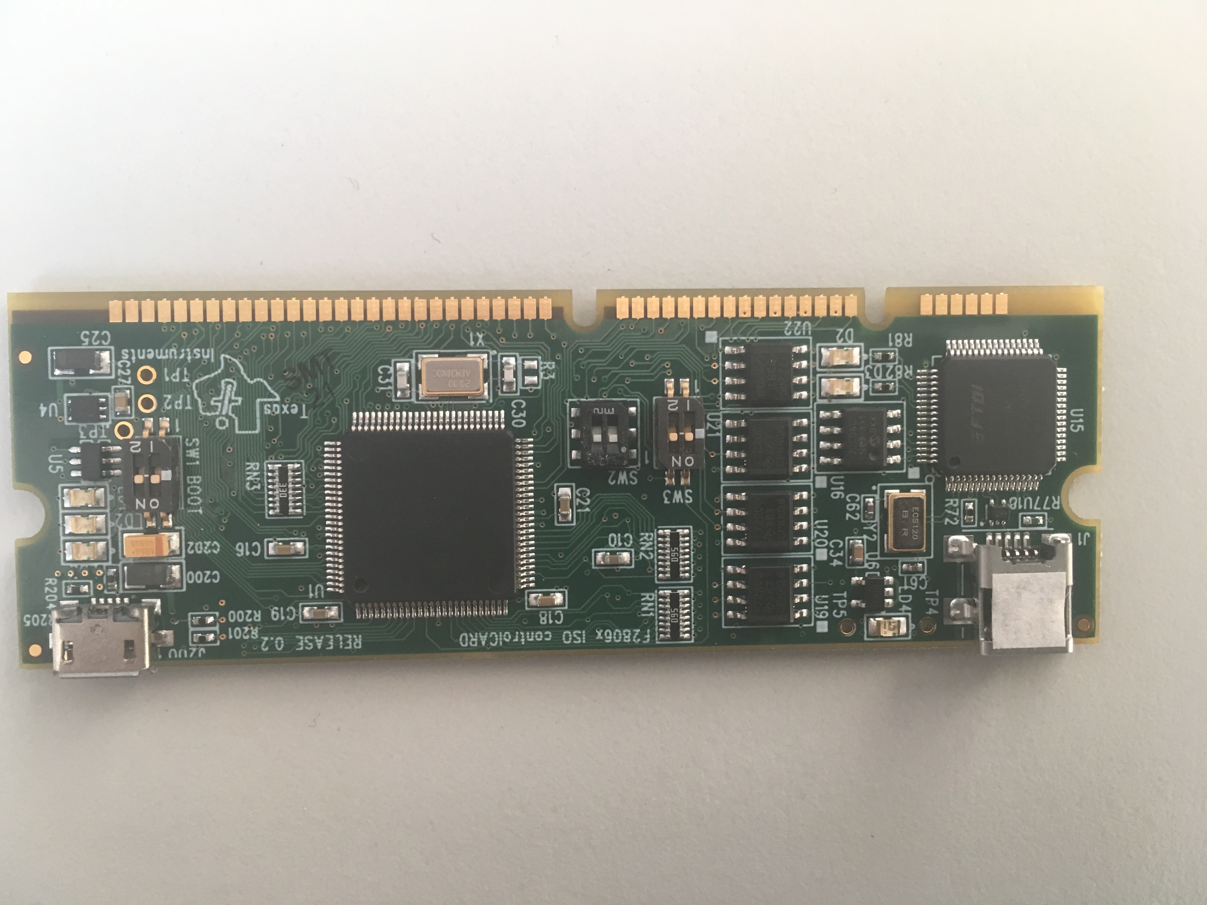
  • Ok so you have the TMDSCNCD28069MISO controlCARD and not the LaunchPad. I don't recall there being any jumpers on the controlCARD, unlike the LaunchPad where you have to be careful with the jumpers.

    On the controlCARD the usb connector J1 (just beside the FTDI chip in your picture) is the one to use for the XDS100v2. If you connect both usb cables to the controlCARD and don't insert the controlCARD into the DRV8312EVM are you able to connect to the controlCARD with CCS?

    Regards,
    John
  • JohnS said:
    Ok so you have the TMDSCNCD28069MISO controlCARD and not the LaunchPad. I don't recall there being any jumpers on the controlCARD, unlike the LaunchPad where you have to be careful with the jumpers.

    The TMDSCNCD28069MISO controlCARD does have the switches SW1 and SW3 which are used to configure the boot mode.

    From looking at the documentation when SW3-1 is ON the TMS320F28069M will be in "Emulation Boot" which will should allow the XDS100v2 to connect. The photo of the TMDSCNCD28069MISO controlCARD appears to show SW3-1 is ON which meaning the switches are in the correct position to allow the XDS100v2 to connect.

  • Dear Johns

    I have tried that I connect both of the USB cable to the microcontroller. It does work and the debug is successful. Thank you very much!

    KInd regards

    Shaochuan Zhang