This thread has been locked.

If you have a related question, please click the "Ask a related question" button in the top right corner. The newly created question will be automatically linked to this question.

CCS/TMS320F28031: Issues with the debugger using blackhawk usb 2000

Part Number: TMS320F28031

Tool/software: Code Composer Studio

Hi, 

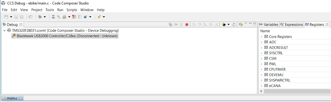
I am trying to use BlackHawk USB2000 emulator to debug the code on processor (28031) having issues in launching the debug session. It does pass the communication test and when I try to launch the debug session the code composer just hangs there and stays there in launching point for hours and hours.

 I am using Code composer studio 5.5.0.00077 and BlackHawk USB 2000 controller (BH-USB-2000). I have also tried uninstalling the code composer studio and fresh installation with fresh workspace  but still same result.

Any help is appreciated. 

Thanks

  • Hello,
    Can you provide some more details? Specifically, how are you launching a debug session? And what is the action that it hangs on? A screenshot will be useful to see.

    Also, note that your CCS version is quite old. Any reason you are using that old version?

    Thanks
    ki
  • Hi Ki-Soo, 

    Basically, I am using the old version because I get some issues in the new version of the compiler and that is the reason I haven't updated the compiler. 

    I have created the target configuration file and the Test connections results are:

    [Start]

    Execute the command:

    %ccs_base%/common/uscif/dbgjtag.exe -f %boarddatafile% -rv -o -F inform,logfile=yes -S pathlength -S integrity

    [Result]


    -----[Print the board config pathname(s)]------------------------------------

    C:\Users\mikhlas\AppData\Local\.TI\693494126\
    0\0\BrdDat\testBoard.dat

    -----[Print the reset-command software log-file]-----------------------------

    This utility has selected a 100- or 510-class product.
    This utility will load the adapter 'bhemujscl.dll'.
    The library build date was 'Aug 20 2013'.
    The library build time was '22:56:19'.
    The library package version is '5.1.232.0'.
    The library component version is '35.34.40.0'.
    The controller does not use a programmable FPGA.
    The controller has a version number of '10' (0x0000000a).
    The controller has an insertion length of '0' (0x00000000).
    This utility will attempt to reset the controller.
    This utility has successfully reset the controller.

    -----[Print the reset-command hardware log-file]-----------------------------

    The scan-path will be reset by toggling the JTAG TRST signal.
    The controller is of an unknown type.
    The link from controller to target is direct (without cable).
    The controller has a logic ONE on its EMU[0] input pin.
    The controller has a logic ONE on its EMU[1] input pin.
    The controller will use rising-edge timing on output pins.
    The controller cannot control the timing on input pins.
    The scan-path link-delay has been set to exactly '0' (0x0000).

    -----[The log-file for the JTAG TCLK output generated from the PLL]----------

    Test Size Coord MHz Flag Result Description
    ~~~~ ~~~~ ~~~~~~~ ~~~~~~~~ ~~~~ ~~~~~~~~~~~ ~~~~~~~~~~~~~~~~~~~
    1 none - 01 00 500.0kHz - similar isit internal clock
    2 none - 01 09 570.3kHz - similar isit internal clock
    3 512 - 01 00 500.0kHz O good value measure path length
    4 128 - 01 00 500.0kHz O good value auto step initial
    5 128 - 01 0D 601.6kHz O good value auto step delta
    6 128 - 01 1C 718.8kHz O good value auto step delta
    7 128 - 01 2E 859.4kHz O good value auto step delta
    8 128 + 00 02 1.031MHz O good value auto step delta
    9 128 + 00 0F 1.234MHz O good value auto step delta
    10 128 + 00 1F 1.484MHz O good value auto step delta
    11 128 + 00 32 1.781MHz O good value auto step delta
    12 128 + 01 04 2.125MHz O good value auto step delta
    13 128 + 01 11 2.531MHz O good value auto step delta
    14 128 + 01 21 3.031MHz O good value auto step delta
    15 128 + 01 34 3.625MHz O good value auto step delta
    16 128 + 02 05 4.313MHz O good value auto step delta
    17 128 + 02 13 5.188MHz O good value auto step delta
    18 128 + 02 23 6.188MHz O good value auto step delta
    19 128 + 02 37 7.438MHz O good value auto step delta
    20 128 + 03 07 8.875MHz O good value auto step delta
    21 128 + 03 15 10.63MHz O good value auto step delta
    22 128 + 03 26 12.75MHz O good value auto step delta
    23 128 + 03 3A 15.25MHz O good value auto step delta
    24 128 + 04 09 18.25MHz O good value auto step delta
    25 128 + 04 17 21.75MHz O good value auto step delta
    26 128 + 04 28 26.00MHz O good value auto step delta
    27 128 + 04 3D 31.25MHz O good value auto step delta
    28 128 + 05 0B 37.50MHz O good value auto step delta
    29 128 + 05 0F 39.50MHz {O} good value auto step delta
    30 512 + 04 2F 27.75MHz O good value auto power initial
    31 512 + 04 3F 31.75MHz O good value auto power delta
    32 512 + 05 07 35.50MHz O good value auto power delta
    33 512 + 05 0B 37.50MHz O good value auto power delta
    34 512 + 05 0D 38.50MHz O good value auto power delta
    35 512 + 05 0E 39.00MHz O good value auto power delta
    36 512 + 05 0E 39.00MHz O good value auto power delta
    37 512 + 05 06 35.00MHz {O} good value auto margin initial

    The first internal/external clock test resuts are:
    The expect frequency was 500000Hz.
    The actual frequency was 500000Hz.
    The delta frequency was 0Hz.

    The second internal/external clock test resuts are:
    The expect frequency was 570312Hz.
    The actual frequency was 568500Hz.
    The delta frequency was 1812Hz.

    In the scan-path tests:
    The test length was 16384 bits.
    The JTAG IR length was 38 bits.
    The JTAG DR length was 1 bits.

    The IR/DR scan-path tests used 37 frequencies.
    The IR/DR scan-path tests used 500.0kHz as the initial frequency.
    The IR/DR scan-path tests used 39.50MHz as the highest frequency.
    The IR/DR scan-path tests used 35.00MHz as the final frequency.

    -----[Measure the source and frequency of the final JTAG TCLKR input]--------

    The frequency of the JTAG TCLKR input is measured as 33.33MHz.

    The frequency of the JTAG TCLKR input and TCLKO output signals are similar.
    The target system likely uses the TCLKO output from the emulator PLL.

    -----[Perform the standard path-length test on the JTAG IR and DR]-----------

    This path-length test uses blocks of 512 32-bit words.

    The test for the JTAG IR instruction path-length succeeded.
    The JTAG IR instruction path-length is 38 bits.

    The test for the JTAG DR bypass path-length succeeded.
    The JTAG DR bypass path-length is 1 bits.

    -----[Perform the Integrity scan-test on the JTAG IR]------------------------

    This test will use blocks of 512 32-bit words.
    This test will be applied just once.

    Do a test using 0xFFFFFFFF.
    Scan tests: 1, skipped: 0, failed: 0
    Do a test using 0x00000000.
    Scan tests: 2, skipped: 0, failed: 0
    Do a test using 0xFE03E0E2.
    Scan tests: 3, skipped: 0, failed: 0
    Do a test using 0x01FC1F1D.
    Scan tests: 4, skipped: 0, failed: 0
    Do a test using 0x5533CCAA.
    Scan tests: 5, skipped: 0, failed: 0
    Do a test using 0xAACC3355.
    Scan tests: 6, skipped: 0, failed: 0
    All of the values were scanned correctly.

    The JTAG IR Integrity scan-test has succeeded.

    -----[Perform the Integrity scan-test on the JTAG DR]------------------------

    This test will use blocks of 512 32-bit words.
    This test will be applied just once.

    Do a test using 0xFFFFFFFF.
    Scan tests: 1, skipped: 0, failed: 0
    Do a test using 0x00000000.
    Scan tests: 2, skipped: 0, failed: 0
    Do a test using 0xFE03E0E2.
    Scan tests: 3, skipped: 0, failed: 0
    Do a test using 0x01FC1F1D.
    Scan tests: 4, skipped: 0, failed: 0
    Do a test using 0x5533CCAA.
    Scan tests: 5, skipped: 0, failed: 0
    Do a test using 0xAACC3355.
    Scan tests: 6, skipped: 0, failed: 0
    All of the values were scanned correctly.

    The JTAG DR Integrity scan-test has succeeded.

    [End]

    When I run the debugger, it shows as the BlackHawk USB2000 controller (disconnected state) see attached picture. If I right click and select connect device it just hangs at that point and doesn't do for hours. I have to unplug the usb connection to get it to response again. 

    Thanks

  • M ikh said:
    Basically, I am using the old version because I get some issues in the new version of the compiler and that is the reason I haven't updated the compiler. 

    Note that while CCS comes with a particular version of the compiler, it is not tied to it. You can use other versions of the compiler with a CCS installation. For example, you can have your CCSv7 installation use the compiler version that came in CCSV5.

    Please see:

    http://processors.wiki.ti.com/index.php/Compiler_Updates

    I would recommend updating CCS to the latest version to ensure that you have the latest drivers and debugger components.

    If that doesn't help, please reproduce the issue while generating a debug server log

    http://processors.wiki.ti.com/index.php/Troubleshooting_CCSv7#Debug_Server_Logging

    Thanks

    ki

  • Newlog.logI have the compiler version as 6.2.9 in advance settings of the project.

    attached the log file with debug server enabled.

  • Can you also try lowering your TCLK speed to legacy 10.368?

    www.youtube.com/watch

    Thanks
    ki
  • 0334.Newlog.log

    generated the log file again with the TCLK at 10.368. Its still responding in the same way. 

  • Hi,

    It worked couple of times today and I was able to launch the debug session couple of times. I power the processor and now it is doing the same thing as before. It just hangs in the launch process. There was no change done before or after the power cycle.

    Thanks