Tool/software: Code Composer Studio
Hello, to all members.
Our board is very similar on Black Beagle Bone design and I am trying to port it with the JTAG.
I use XSD100v2 emulator and the instructions I followed are from Linux Board Porting Training Series.
I use the CCS v.7.3, the XDS100v2 by Blackhawlk
Test Connection result is -
[Start: Texas Instruments XDS100v2 USB Debug Probe_0]
Execute the command:
%ccs_base%/common/uscif/dbgjtag -f %boarddatafile% -rv -o -F inform,logfile=yes -S pathlength -S integrity
[Result]
-----[Print the board config pathname(s)]------------------------------------
/home/evgenyv/.ti/ti/0/0/BrdDat/testBoard.dat
-----[Print the reset-command software log-file]-----------------------------
This utility has selected a 100- or 510-class product.
This utility will load the adapter 'libjioserdesusb.so'.
The library build date was 'Jul 21 2017'.
The library build time was '19:29:13'.
The library package version is '7.0.48.0'.
The library component version is '35.35.0.0'.
The controller does not use a programmable FPGA.
The controller has a version number of '4' (0x00000004).
The controller has an insertion length of '0' (0x00000000).
This utility will attempt to reset the controller.
This utility has successfully reset the controller.
-----[Print the reset-command hardware log-file]-----------------------------
The scan-path will be reset by toggling the JTAG TRST signal.
The controller is the FTDI FT2232 with USB interface.
The link from controller to target is direct (without cable).
The software is configured for FTDI FT2232 features.
The controller cannot monitor the value on the EMU[0] pin.
The controller cannot monitor the value on the EMU[1] pin.
The controller cannot control the timing on output pins.
The controller cannot control the timing on input pins.
The scan-path link-delay has been set to exactly '0' (0x0000).
-----[The log-file for the JTAG TCLK output generated from the PLL]----------
There is no hardware for programming the JTAG TCLK frequency.
-----[Measure the source and frequency of the final JTAG TCLKR input]--------
There is no hardware for measuring the JTAG TCLK frequency.
-----[Perform the standard path-length test on the JTAG IR and DR]-----------
This path-length test uses blocks of 64 32-bit words.
The test for the JTAG IR instruction path-length succeeded.
The JTAG IR instruction path-length is 6 bits.
The test for the JTAG DR bypass path-length succeeded.
The JTAG DR bypass path-length is 1 bits.
-----[Perform the Integrity scan-test on the JTAG IR]------------------------
This test will use blocks of 64 32-bit words.
This test will be applied just once.
Do a test using 0xFFFFFFFF.
Scan tests: 1, skipped: 0, failed: 0
Do a test using 0x00000000.
Scan tests: 2, skipped: 0, failed: 0
Do a test using 0xFE03E0E2.
Scan tests: 3, skipped: 0, failed: 0
Do a test using 0x01FC1F1D.
Scan tests: 4, skipped: 0, failed: 0
Do a test using 0x5533CCAA.
Scan tests: 5, skipped: 0, failed: 0
Do a test using 0xAACC3355.
Scan tests: 6, skipped: 0, failed: 0
All of the values were scanned correctly.
The JTAG IR Integrity scan-test has succeeded.
-----[Perform the Integrity scan-test on the JTAG DR]------------------------
This test will use blocks of 64 32-bit words.
This test will be applied just once.
Do a test using 0xFFFFFFFF.
Scan tests: 1, skipped: 0, failed: 0
Do a test using 0x00000000.
Scan tests: 2, skipped: 0, failed: 0
Do a test using 0xFE03E0E2.
Scan tests: 3, skipped: 0, failed: 0
Do a test using 0x01FC1F1D.
Scan tests: 4, skipped: 0, failed: 0
Do a test using 0x5533CCAA.
Scan tests: 5, skipped: 0, failed: 0
Do a test using 0xAACC3355.
Scan tests: 6, skipped: 0, failed: 0
All of the values were scanned correctly.
The JTAG DR Integrity scan-test has succeeded.
[End: Texas Instruments XDS100v2 USB Debug Probe_0]
After attempt to Connect to target, there is this error pop up
Error connecting to the target:
(Error -1170 @ 0x0)
Unable to access the DAP. Reset the device, and retry the operation. If error persists, confirm configuration, power-cycle the board, and/or try more reliable JTAG settings (e.g. lower TCLK).
(Emulation package 7.0.48.0)
SYS_BOOT_5 is pulled up.
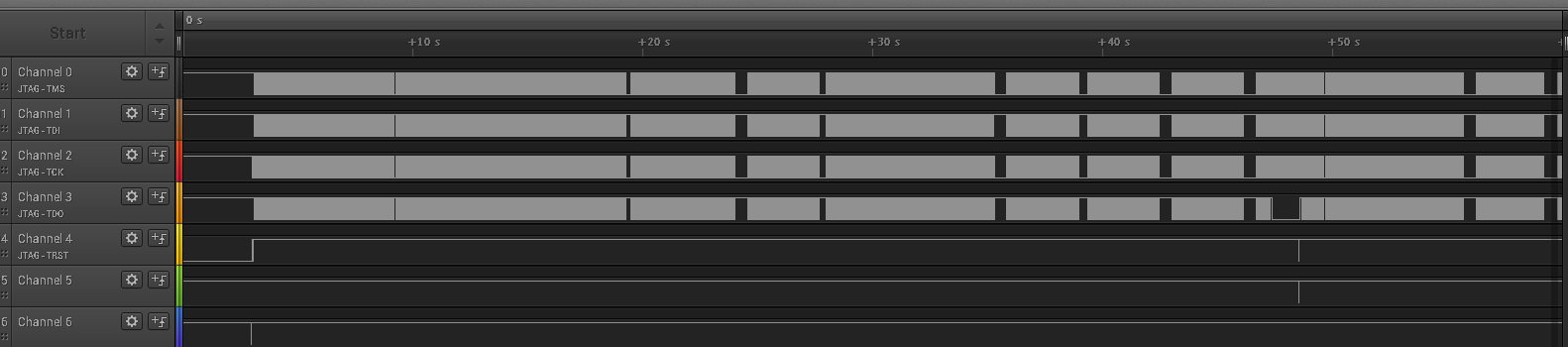
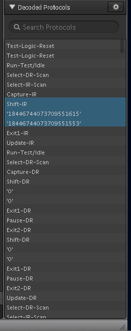
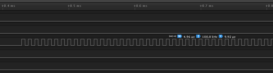
When I configured 100KHz on JTAG TCLK Frequency and got this on the logic analyzer:

When I configured the clock to 10.368 MHz I got the next error message:
Error connecting to the target:
(Error -1170 @ 0x0)
Unable to access the DAP. Reset the device, and retry the operation. If error persists, confirm configuration, power-cycle the board, and/or try more reliable JTAG settings (e.g. lower TCLK).
(Emulation package 7.0.48.0)

Is it configuration?
Are these connections?
Is it license?
Is it debugger?
I am a new in the fielsdof Linux embedded development and new to the TI world, so I am sorry in advance if the questions are formulated unprofessionally.