This thread has been locked.

If you have a related question, please click the "Ask a related question" button in the top right corner. The newly created question will be automatically linked to this question.

CCS: GUI Composer v2 with Motorware + TMS320F28069

Other Parts Discussed in Thread: TMS320F28069, MOTORWARE, C2000WARE

Tool/software: Code Composer Studio

Hello,

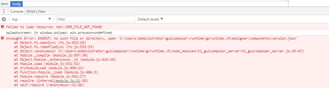
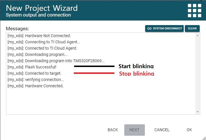
Currently, I'm trying to use GUI Composer v2 for my target board which consist of TMS320F28069, TI XDS100v2 usb debug probe and  Motorware.

But, I couldn't binding any variables which was included .out file with GUI Composer v2 components. Is there any suitable documents for my work?

I already checked some documents such as, online help and user manual for CUI Composer v2. 

Sincererly,

Eui-heon

  • I'm sorry. My CCS Version is 7.2.0
  • Have you had a look at the tutorial at this link? It is written for F28379D but can easily be adapted to F28069. It shows how to bind a global variable to a GUI Composer widget. Hope this helps!

  • Dear ArtiG,

    Thank you for your reply.

    I tested CCS Desktop View with my target board. It's work well. In case of Stand-Alone APP, when I run the win32_start.bat file, this program  just display attached image and stop. Can you help me?

    Sincerely,

    Eui-heon

  • Dear ArtiG,

    When I opened the win32_start.bat I saw some codes as following.

    >>

    echo Starting GUI Composer...
    cd /d %~dp0
    REM Please hit F12 when in GUI Composer to open the debugger.
    call "splash\win32_splash.bat"

    >>

    So, I press F12 Key after run the win32_start.bat then I got some error messages as attached.

    Please check the attached file.

    Sincerely, 

    Eui-heon

  • Eui-Heon Jung said:
    In case of Stand-Alone APP, when I run the win32_start.bat file, this program  just display attached image and stop.

    I see the same issue as well.

    When the tutorial was originally written, it used an earlier version of GUI Composer runtime and I had verified that it worked. Something must have changed in the newer runtime. I will try to get a GUI Composer expert to take a look at this and comment.

  • Dear ArtiG,
    Thank you for your replay.
    I hope for a GUI Composer expert to resolve this thing as soon as possible.
    Sincerely,
    Eui-heon
  • Hi Eui-heon, 

    It might be the same issue as described in this forum post; Could you please try it an let us know if it resolves your issue as well?

  • Dear MartinS,

    Thank you for your replay.

    Depending on your comment, I changed the standalone_app set to true @  .. /splash/package.json file, and I can see the complete GUI screen.

    But, unlike CCS Desktop View, when I use the standalone app, the target board run and stop after 5 ~ 6 seconds suddenly.

    (To check the status of target board, I inserted LED blinking action @ interrupt service routine. The LED blinking was stopped after 5 ~ 6 seconds)

    Can you help me?

    Sincerely,

    Eui-heon

  • Dear MartinS,

    I checked the connection procedure as following.

    At " [my_xds]:Flash Successful! " step, the LED was blinked, but at [my_xds]:Connected to target. step the LED was stopped.

    In my guess, the connection between Stand-alone APP and target board was disconnected @ [my_xds]:Connected to target step.

    Please let me know if I should do something.

    Sincerely,

    Eui-heon

  • Hi Eui-heon, 

    It seems like your program is most likely built to run out of RAM memory. We currently have an issue that is GUI Composer v2 specific, where RAM memory is reset between programming and starting a debug connection. Unfortunately, there isn't a simple workaround for this issue at this point. The only workaround in the near term is to rebuild the program to be run out of flash memory. Is this an option that you could try? 

    We have a bug filed for this issue, but we do not have a fix for it yet. 

    Martin

  • Dear Martin,

    When I tested a program with Flash build configuration on Stand-alone App, the result is same.
    So, I unchecked the "Auto Program" option for XDS setting at GUI Project and test again.
    In result, the target board work before the "OK" button was pressed on Program Loading Status Dialog BOX,
    but when I press the OK button, target board was stopped.
    During the test, the message which was displayed on status bar was changed as following.
    <Before pressed "OK" Button on dialog box>
    "Connected to target. Hardware Connected"
    <After that>
    "Connected to target. Reconfiguring connection to target"
    ( => In this step, the target board was stopped.)
    "Connected to target. Hardware Connected"

    Is there any reason re-configuring connection to target after flashing and run?

    Sincerely,
    Eui-heon
  • Hello Eui-Heon, 

    I am a little confused. In second sentence you stated that you unchecked Auto Program, then the result was that you saw Program Load dialog box and you still had the same issue. 

    Is the issue that even though you had Auto Program unchecked, then program loading still happened even though it should not have? 

    Thank you,
    Martin

  • Dear Martin,
    I'm sorry to make you confused.
    After unchecked Auto Program, I'm using "Dashboard -> File -> Program Device..." menu to flash the target board.
    The .out file was built by Flash build option.

    Sincerely,
    Eui-heon
  • Dear Martin,
    Currently, Is there any solution for stand-alone App running with my target board?
    Sincerely,
    Eui-heon
  • Eui-heon,

    Sorry about the delayed reply. I didn't have any problems with the stand-alone app when working with a Flash based program. It worked in both cases - with the "Auto Program" option in GUI project checked or unchecked. So I'm not sure what is different in your environment.

    Are you not able to see it working in either case? With the "Auto Program" option checked it will download the program each time it starts up the stand-alone app. If it is unchecked, the program should already be in flash (if it was previously programmed once) and the GUI app should just connect to it and then start updating the widgets. I have a simple LED blink project that works fine in both cases.

    Does the CCS Desktop view work ok for you?
  • Dear AartiG,

    The CCS Desktop view is OK. My purpose for checking the "Auto Program" and "Manual Program" option is to see some messages on stand-alone app. 

    Today I checked stand-alone app for emulation boot mode and flash boot mode of target board.

    In emulation boot mode, the target board work after finish flashing and stop after 5 ~ 6 seconds but in flash boot mode,

    the target board work except stop shortly.

    I want to show you two video clips for both operations, but I couldn't upload by size. If you let me know your e-mail address, I will send to you.

    Sincerely,

    Eui-heon

  • Eui-Heon Jung said:
    I want to show you two video clips for both operations, but I couldn't upload by size.

    Could you try zipping them up to see if their size is reduced enough to be able to attach? I can also start a private conversation with you and you could try sharing it there.

    At the same time, I thought I would share my program with you so you can try it out in your environment. At my end, this works fine on a F28069 Experimenter's kit. The boot mode jumpers on the controlcard are set for Boot to Flash.

    I verified that the GUI Composer app works both when run from GUI Composer and when run as a standalone app.

    Details about the CCS project:

    - Import the flash_f28069 example from C2000Ware (under \device_support\f2806x\examples\c28\flash_f28069)
    - Modify the source file Example_28069Flash.c to add global variable led_status that ties to LED blink operation (my modified file is attached for reference)
    - Rebuild and run the project in CCS to verify LED operation

    Details about GUI Composer project:

    - Add a LED Tile and bind it to led_status variable
    - Target communication settings are as shown below
      ( I am also attaching my .out file so you could also try using it directly in the GUI Composer project setting)


    - Run the GUI Composer app and verify that LED on the app syncs with LED on board
    - Export project as Stand-Alone App and verify stand-alone operation

    Please give this a try and let me know if it works on your set-up.

    //###########################################################################
    //
    // FILE:	Example_28069Flash.c
    //
    // TITLE:	ePWM Timer Interrupt From Flash Example
    //
    //! \addtogroup f2806x_example_list
    //! <h1>ePWM Timer Interrupt From Flash (flash_f28069)</h1>
    //!
    //! This example runs the ePWM interrupt example from flash. ePwm1 Interrupt 
    //! will run from RAM and puts the flash into sleep mode. ePwm2 Interrupt 
    //! will run from RAM and puts the flash into standby mode. ePWM3 Interrupt
    //! will run from FLASH. All timers have the same period. The timers are 
    //! started sync'ed. An interrupt is taken on a zero event for each ePWM 
    //! timer.GPIO34 is toggled while in the background loop.
    //! Note:
    //!   - ePWM1: takes an interrupt every event
    //!   - ePWM2: takes an interrupt every 2nd event
    //!   - ePWM3: takes an interrupt every 3rd event 
    //! Thus the Interrupt count for ePWM1, ePWM4-ePWM6 should be equal
    //! The interrupt count for ePWM2 should be about half that of ePWM1
    //! and the interrupt count for ePWM3 should be about 1/3 that of ePWM1
    //! 
    //! Follow these steps to run the program.
    //!   - Build the project
    //!   - Flash the .out file into the device.
    //!   - Set the hardware jumpers to boot to Flash (put position 1 and 2 of 
    //!     SW2 on control Card to ON position).
    //!   - Use the included GEL file to load the project, symbols
    //!     defined within the project and the variables into the watch
    //!     window.
    //! 
    //! Steps that were taken to convert the ePWM example from RAM
    //! to Flash execution: 
    //! - Change the linker cmd file to reflect the flash memory map.
    //! - Make sure any initialized sections are mapped to Flash.
    //!   In SDFlash utility this can be checked by the View->Coff/Hex
    //!   status utility. Any section marked as "load" should be
    //!   allocated to Flash.
    //! - Make sure there is a branch instruction from the entry to Flash
    //!   at 0x3F7FF6 to the beginning of code execution. This example
    //!   uses the DSP0x_CodeStartBranch.asm file to accomplish this.
    //! - Set boot mode Jumpers to "boot to Flash"
    //! - For best performance from the flash, modify the waitstates
    //!   and enable the flash pipeline as shown in this example.
    //!   Note: any code that manipulates the flash waitstate and pipeline
    //!   control must be run from RAM. Thus these functions are located
    //!   in their own memory section called ramfuncs.
    //! 
    //! \b Watch \b Variables \n
    //!  - EPwm1TimerIntCount
    //!  - EPwm2TimerIntCount
    //!  - EPwm3TimerIntCount
    //
    //###########################################################################
    // $TI Release: F2806x Support Library v2.02.00.00 $
    // $Release Date: Sat Sep 16 15:27:43 CDT 2017 $
    // $Copyright:
    // Copyright (C) 2009-2017 Texas Instruments Incorporated - http://www.ti.com/
    //
    // Redistribution and use in source and binary forms, with or without 
    // modification, are permitted provided that the following conditions 
    // are met:
    // 
    //   Redistributions of source code must retain the above copyright 
    //   notice, this list of conditions and the following disclaimer.
    // 
    //   Redistributions in binary form must reproduce the above copyright
    //   notice, this list of conditions and the following disclaimer in the 
    //   documentation and/or other materials provided with the   
    //   distribution.
    // 
    //   Neither the name of Texas Instruments Incorporated nor the names of
    //   its contributors may be used to endorse or promote products derived
    //   from this software without specific prior written permission.
    // 
    // THIS SOFTWARE IS PROVIDED BY THE COPYRIGHT HOLDERS AND CONTRIBUTORS 
    // "AS IS" AND ANY EXPRESS OR IMPLIED WARRANTIES, INCLUDING, BUT NOT 
    // LIMITED TO, THE IMPLIED WARRANTIES OF MERCHANTABILITY AND FITNESS FOR
    // A PARTICULAR PURPOSE ARE DISCLAIMED. IN NO EVENT SHALL THE COPYRIGHT 
    // OWNER OR CONTRIBUTORS BE LIABLE FOR ANY DIRECT, INDIRECT, INCIDENTAL, 
    // SPECIAL, EXEMPLARY, OR CONSEQUENTIAL DAMAGES (INCLUDING, BUT NOT 
    // LIMITED TO, PROCUREMENT OF SUBSTITUTE GOODS OR SERVICES; LOSS OF USE,
    // DATA, OR PROFITS; OR BUSINESS INTERRUPTION) HOWEVER CAUSED AND ON ANY
    // THEORY OF LIABILITY, WHETHER IN CONTRACT, STRICT LIABILITY, OR TORT 
    // (INCLUDING NEGLIGENCE OR OTHERWISE) ARISING IN ANY WAY OUT OF THE USE 
    // OF THIS SOFTWARE, EVEN IF ADVISED OF THE POSSIBILITY OF SUCH DAMAGE.
    // $
    //###########################################################################
    
    //
    // Included Files
    //
    #include "DSP28x_Project.h"     // Device Headerfile and Examples Include File
    #include "string.h"
    
    //
    // Defines that configure which ePWM timer interrupts are enabled at the 
    // PIE level: 1 = enabled,  0 = disabled
    //
    #define PWM1_INT_ENABLE  1
    #define PWM2_INT_ENABLE  1
    #define PWM3_INT_ENABLE  1
    
    //
    // Defines that configure the period for each timer
    //
    #define PWM1_TIMER_TBPRD   0x1FFF
    #define PWM2_TIMER_TBPRD   0x1FFF
    #define PWM3_TIMER_TBPRD   0x1FFF
    
    //
    // Defines that make this long enough so that we can see an LED toggle
    //
    #define DELAY 1000000L
    
    //
    // Functions that will be run from RAM need to be assigned to
    // a different section.  This section will then be mapped using
    // the linker cmd file.
    //
    #pragma CODE_SECTION(epwm1_timer_isr, "ramfuncs");
    #pragma CODE_SECTION(epwm2_timer_isr, "ramfuncs");
    
    //
    // Function Prototypes
    //
    interrupt void epwm1_timer_isr(void);
    interrupt void epwm2_timer_isr(void);
    interrupt void epwm3_timer_isr(void);
    void InitEPwmTimer(void);
    
    //
    // Globals
    //
    Uint32  EPwm1TimerIntCount;
    Uint32  EPwm2TimerIntCount;
    Uint32  EPwm3TimerIntCount;
    Uint32  LoopCount;
    
    //
    // These are defined by the linker (see F2808.cmd)
    //
    extern Uint16 RamfuncsLoadStart;
    extern Uint16 RamfuncsLoadEnd;
    extern Uint16 RamfuncsRunStart;
    extern Uint16 RamfuncsLoadSize;
    
    //
    // Main
    //
    void main(void)
    {
        //
        // Step 1. Initialize System Control:
        // PLL, WatchDog, enable Peripheral Clocks
        // This example function is found in the F2806x_SysCtrl.c file.
        //
        InitSysCtrl();
    
        //
        // Step 2. Initalize GPIO:
        // This example function is found in the F2806x_Gpio.c file and
        // illustrates how to set the GPIO to it's default state.
        //
        // InitGpio();  // Skipped for this example
    
        //
        // Step 3. Clear all interrupts and initialize PIE vector table:
        // Disable CPU interrupts
        //
        DINT;
    
        //
        // Initialize the PIE control registers to their default state.
        // The default state is all PIE interrupts disabled and flags
        // are cleared.
        // This function is found in the F2806x_PieCtrl.c file.
        //
        InitPieCtrl();
    
        //
        // Disable CPU interrupts and clear all CPU interrupt flags
        //
        IER = 0x0000;
        IFR = 0x0000;
    
        //
        // Initialize the PIE vector table with pointers to the shell Interrupt
        // Service Routines (ISR).
        // This will populate the entire table, even if the interrupt
        // is not used in this example.  This is useful for debug purposes.
        // The shell ISR routines are found in F2806x_DefaultIsr.c.
        // This function is found in F2806x_PieVect.c.
        //
        InitPieVectTable();
    
        //
        // Interrupts that are used in this example are re-mapped to
        // ISR functions found within this file.
        //
        EALLOW;  // This is needed to write to EALLOW protected registers
        PieVectTable.EPWM1_INT = &epwm1_timer_isr;
        PieVectTable.EPWM2_INT = &epwm2_timer_isr;
        PieVectTable.EPWM3_INT = &epwm3_timer_isr;
        EDIS;    // This is needed to disable write to EALLOW protected registers
    
        //
        // Step 4. Initialize all the Device Peripherals:
        // This function is found in F2806x_InitPeripherals.c
        //
        // InitPeripherals();  // Not required for this example
        InitEPwmTimer();    // For this example, only initialize the ePWM Timers
    
        //
        // Step 5. User specific code, enable interrupts
        //
    
        //
        // Copy time critical code and Flash setup code to RAM
        // This includes the following ISR functions: epwm1_timer_isr(), 
        // epwm2_timer_isr(), epwm3_timer_isr and and InitFlash();
        // The  RamfuncsLoadStart, RamfuncsLoadSize, and RamfuncsRunStart
        // symbols are created by the linker. Refer to the F2808.cmd file.
        //
        memcpy(&RamfuncsRunStart, &RamfuncsLoadStart, (Uint32)&RamfuncsLoadSize);
    
        //
        // Call Flash Initialization to setup flash waitstates
        // This function must reside in RAM
        //
        InitFlash();
    
        //
        // Initalize counters
        //
        EPwm1TimerIntCount = 0;
        EPwm2TimerIntCount = 0;
        EPwm3TimerIntCount = 0;
        LoopCount = 0;
    
        //
        // Enable CPU INT3 which is connected to EPWM1-3 INT
        //
        IER |= M_INT3;
    
        //
        // Enable EPWM INTn in the PIE: Group 3 interrupt 1-3
        //
        PieCtrlRegs.PIEIER3.bit.INTx1 = PWM1_INT_ENABLE;
        PieCtrlRegs.PIEIER3.bit.INTx2 = PWM2_INT_ENABLE;
        PieCtrlRegs.PIEIER3.bit.INTx3 = PWM3_INT_ENABLE;
    
        //
        // Enable global Interrupts and higher priority real-time debug events
        //
        EINT;   // Enable Global interrupt INTM
        ERTM;   // Enable Global realtime interrupt DBGM
    
        //
        // Step 6. IDLE loop. Just sit and loop forever (optional)
        //
        EALLOW;
        GpioCtrlRegs.GPBMUX1.bit.GPIO34 = 0;
        GpioCtrlRegs.GPBDIR.bit.GPIO34 = 1;
        EDIS;
    
        for(;;)
        {
            //
            // This loop will be interrupted, so the overall delay between pin 
            // toggles will be longer.
            //
            DELAY_US(DELAY);
            LoopCount++;
            GpioDataRegs.GPBTOGGLE.bit.GPIO34 = 1;
        }
    }
    
    //
    // InitEPwmTimer - 
    //
    void
    InitEPwmTimer()
    {
        EALLOW;
        SysCtrlRegs.PCLKCR0.bit.TBCLKSYNC = 0;      // Stop all the TB clocks
        EDIS;
    
        InitEPwm1Gpio();
        InitEPwm2Gpio();
        InitEPwm3Gpio();
    
        //
        // Setup Sync
        //
        EPwm1Regs.TBCTL.bit.SYNCOSEL = TB_SYNC_IN;  // Pass through
        EPwm2Regs.TBCTL.bit.SYNCOSEL = TB_SYNC_IN;  // Pass through
        EPwm3Regs.TBCTL.bit.SYNCOSEL = TB_SYNC_IN;  // Pass through
    
        //
        // Allow each timer to be sync'ed
        //
        EPwm1Regs.TBCTL.bit.PHSEN = TB_ENABLE;
        EPwm2Regs.TBCTL.bit.PHSEN = TB_ENABLE;
        EPwm3Regs.TBCTL.bit.PHSEN = TB_ENABLE;
    
        EPwm1Regs.TBPHS.half.TBPHS = 100;
        EPwm2Regs.TBPHS.half.TBPHS = 200;
        EPwm3Regs.TBPHS.half.TBPHS = 300;
    
        EPwm1Regs.TBPRD = PWM1_TIMER_TBPRD;
        EPwm1Regs.TBCTL.bit.CTRMODE = TB_COUNT_UP;    // Count up
        EPwm1Regs.ETSEL.bit.INTSEL = ET_CTR_ZERO;     // Select INT on Zero event
        EPwm1Regs.ETSEL.bit.INTEN = PWM1_INT_ENABLE;  // Enable INT
        EPwm1Regs.ETPS.bit.INTPRD = ET_1ST;           // Generate INT on 1st event
    
        EPwm2Regs.TBPRD = PWM2_TIMER_TBPRD;
        EPwm2Regs.TBCTL.bit.CTRMODE = TB_COUNT_UP;     // Count up
        EPwm2Regs.ETSEL.bit.INTSEL = ET_CTR_ZERO;      // Enable INT on Zero event
        EPwm2Regs.ETSEL.bit.INTEN = PWM2_INT_ENABLE;   // Enable INT
        EPwm2Regs.ETPS.bit.INTPRD = ET_2ND;            // Generate INT on 2nd event
    
        EPwm3Regs.TBPRD = PWM3_TIMER_TBPRD;
        EPwm3Regs.TBCTL.bit.CTRMODE = TB_COUNT_UP;     // Count up
        EPwm3Regs.ETSEL.bit.INTSEL = ET_CTR_ZERO;      // Enable INT on Zero event
        EPwm3Regs.ETSEL.bit.INTEN = PWM3_INT_ENABLE;   // Enable INT
        EPwm3Regs.ETPS.bit.INTPRD = ET_3RD;            // Generate INT on 3rd event
    
        EALLOW;
        SysCtrlRegs.PCLKCR0.bit.TBCLKSYNC = 1;         // Start all the timers synced
        EDIS;
    }
    
    //
    // epwm1_timer_isr - This ISR MUST be executed from RAM as it will put the 
    // Flash into Sleep Interrupt routines uses in this example:
    //
    interrupt void
    epwm1_timer_isr(void)
    {
        //
        // Put the Flash to sleep
        //
        EALLOW;
        FlashRegs.FPWR.bit.PWR = FLASH_SLEEP;
        EDIS;
    
        EPwm1TimerIntCount++;
    
        //
        // Clear INT flag for this timer
        //
        EPwm1Regs.ETCLR.bit.INT = 1;
    
        //
        // Acknowledge this interrupt to receive more interrupts from group 3
        //
        PieCtrlRegs.PIEACK.all = PIEACK_GROUP3;
    }
    
    //
    // epwm2_timer_isr - This ISR MUST be executed from RAM as it will put the 
    // Flash into Standby
    //
    interrupt void
    epwm2_timer_isr(void)
    {
        EPwm2TimerIntCount++;
    
        //
        // Put the Flash into standby
        //
        EALLOW;
        FlashRegs.FPWR.bit.PWR = FLASH_STANDBY;
        EDIS;
    
        //
        // Clear INT flag for this timer
        //
        EPwm2Regs.ETCLR.bit.INT = 1;
    
        //
        // Acknowledge this interrupt to receive more interrupts from group 3
        //
        PieCtrlRegs.PIEACK.all = PIEACK_GROUP3;
    }
    
    //
    // epwm3_timer_isr -
    //
    interrupt void
    epwm3_timer_isr(void)
    {
        Uint16 i;
    
        EPwm3TimerIntCount++;
    
        //
        // Short Delay to simulate some ISR Code
        //
        for(i = 1; i < 0x01FF; i++)
        {
            
        }
    
        //
        // Clear INT flag for this timer
        //
        EPwm3Regs.ETCLR.bit.INT = 1;
    
        //
        // Acknowledge this interrupt to receive more interrupts from group 3
        //
        PieCtrlRegs.PIEACK.all = PIEACK_GROUP3;
    }
    
    //
    // End of File
    //


    https://e2e.ti.com/cfs-file/__key/communityserver-discussions-components-files/81/Example_5F00_2806xFlash.out

  • Dear AartiG,

    Because the size of zip file including two files is 157Mb, I couldn't attach.
    When I tested stand-alone GUI with F2806x ISO control card (RELEASE 0.4) + DRV8301kit_revD from TI,
    the result is same with my previous test. And your file and test procedure give to me same result.

    Sincerely,
    Eui-heon
  • Eui-heon,

    I'm not sure why the app which works well for me does not work in your environment. The F28069 controlcard I am using is Release 1.1. Not sure if there are differences in the hardware itself that could be making an impact here. 

    As a last resort, if you are willing to share a simple CCS project and GUI Composer app that reproduces the behavior and that can be run on a F28069 Experimenters kit, I can check if I can reproduce your behavior at my end. It would be helpful to have the complete CCS project (you can zip up the project folder and attach here) and GUI Composer app (export it as a project and attach zip file here). 

    In the meantime, I have also sent you a friend request. After you accept it, we can start a private conversation and share files privately. You can also try attaching your videos to the private conversation, perhaps try zipping/attaching each one separately to reduce the overall size of attachment.

  • This discussion was continued offline. To summarize:

    - Customer shared their CCS project and GUI Composer app, which I ran on a F28069 Experimenter kit and the GC app worked as expected. The LED remained blinking as expected.

    - Based on multiple tests (that worked at my end but not at customer's), we concluded that there must be something in the customer's environment and/or hardware that was causing unexpected behavior when running standalone GUI Composer app.

    Customer agreed that this thread can be closed for now. They plan to do additional tests on a different PC system in the near future and will start a new post at that time if needed.