Part Number: TMS320F28379D
Tool/software: TI C/C++ Compiler
I want to write the Registers of an external IC. Therefore the data has to be send on one Pin in a strictly defined order.
To keep things readable I wrote an union for that task.
If I run the method Reg_Comm.setupt_Bitstream() the resulting Bitstreams are different depending on the compiler-opt-lvl I chose.
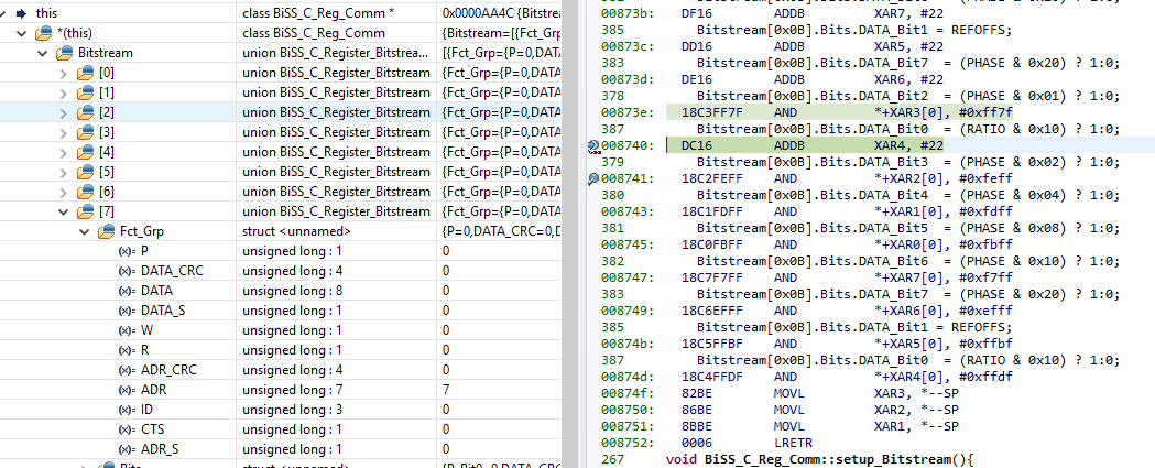
While using opt-lvl 0 The Bitfiled is filled with the data as expected.
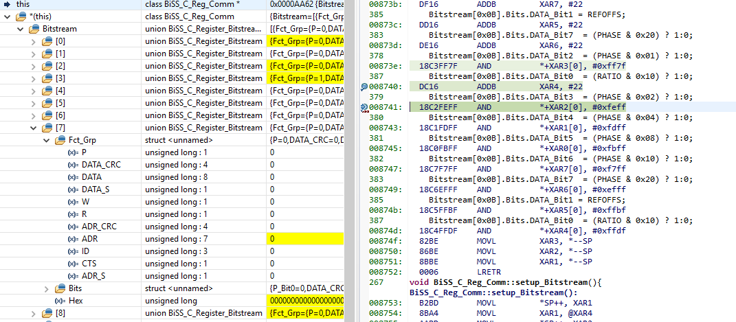
But when I change the opt-lvl to 2 the data inside the Bitfiled is different at many places.
(the Data differes after the call of the private method set_Register_Data() )
I allready tried the followeing things.
- Make the union voaltile
- Make the Bitstream-Array voaltile
- delete the fuctiion set_Register_Data() and write it directly into setup_Bitstream()
None of these steps helped.
Detailed Compiler-settings:
Working:
-v28 -ml -mt --cla_support=cla1 --float_support=fpu32 --tmu_support=tmu0 --vcu_support=vcu2 -Ooff --opt_for_speed=4
Data-Corruption:
-v28 -ml -mt --cla_support=cla1 --float_support=fpu32 --tmu_support=tmu0 --vcu_support=vcu2 -O2 --opt_for_speed=4
Here is the Code:
//HEADER START HERE

#define HIGHEST_REGISTER_NUMBER   0x0C

typedef union{
    struct {
        uint32_t P          : 1;
        uint32_t DATA_CRC   : 4;
        uint32_t DATA       : 8;
        uint32_t DATA_S     : 1;
        uint32_t W          : 1;
        uint32_t R          : 1;
        uint32_t ADR_CRC    : 4;
        uint32_t ADR        : 7;
        uint32_t ID         : 3;
        uint32_t CTS        : 1;
        uint32_t ADR_S      : 1;
    }Fct_Grp;

    struct{
        uint32_t P_Bit0         : 1;
        uint32_t DATA_CRC_Bit0  : 1;
        uint32_t DATA_CRC_Bit1  : 1;
        uint32_t DATA_CRC_Bit2  : 1;
        uint32_t DATA_CRC_Bit3  : 1;
        uint32_t DATA_Bit0      : 1;
        uint32_t DATA_Bit1      : 1;
        uint32_t DATA_Bit2      : 1;
        uint32_t DATA_Bit3      : 1;
        uint32_t DATA_Bit4      : 1;
        uint32_t DATA_Bit5      : 1;
        uint32_t DATA_Bit6      : 1;
        uint32_t DATA_Bit7      : 1;
        uint32_t DATA_S_Bit0    : 1;
        uint32_t W_Bit0         : 1;
        uint32_t R_Bit0         : 1;
        uint32_t ADR_CRC_Bit0   : 1;
        uint32_t ADR_CRC_Bit1   : 1;
        uint32_t ADR_CRC_Bit2   : 1;
        uint32_t ADR_CRC_Bit3   : 1;
        uint32_t ADR_Bit0       : 1;
        uint32_t ADR_Bit1       : 1;
        uint32_t ADR_Bit2       : 1;
        uint32_t ADR_Bit3       : 1;
        uint32_t ADR_Bit4       : 1;
        uint32_t ADR_Bit5       : 1;
        uint32_t ADR_Bit6       : 1;
        uint32_t ID_Bit0        : 1;
        uint32_t ID_Bit1        : 1;
        uint32_t ID_Bit2        : 1;
        uint32_t CTS_Bit0       : 1;
        uint32_t ADR_S_Bit0     : 1;
    }Bits;

    uint32_t Hex;

}Register_Bitstream;

class Reg_Comm{
public:
    void setup_Bitstream();

    Register_Bitstream Bitstream[HIGHEST_REGISTER_NUMBER + 1];
private:
    void set_Register_Adr();
    void set_Register_Data();
};

//HEADER ENDS HERE

//CPP START HERE

#define ENCDS           0
#define M2S             0x00
#define SELRES          0x03
#define HYS             0x00
#define SELSSI          1
#define CRC6            0
#define NZB             0
#define RPL             0
#define AERR            0
#define FERR            0
#define FCTR            0x0004
#define GRAY            0
#define TMODE           0x00
#define TIMO            0
#define TMA             0
#define TOA             0
#define RATIO           0x00
#define GAIN            0x06
#define SINOFFS         0x00
#define COSOFFS         0x00
#define REFOFFS         0
#define PHASE           0x00

void Reg_Comm::setup_Bitstream(){
    set_Register_Adr();
    set_Register_Data();

    for(int i = HIGHEST_REGISTER_NUMBER; i >= 0x00; i--){
        Bitstream[i].Fct_Grp.ADR_S  = 1;
        Bitstream[i].Fct_Grp.CTS   = 1;

        Bitstream[i].Fct_Grp.ID      = 0b000;

        /*Bitstream[i].Fct_Grp.ADR_CRC = calculate_CRC(   (uint16_t) Bitstream[i].Fct_Grp.ADR
                                                    + ( ((uint16_t) Bitstream[i].Fct_Grp.ID) << 7)
                                                    + ( ((uint16_t) Bitstream[i].Fct_Grp.CTS)    << 10)
                                                    , 11);
		*/

        Bitstream[i].Fct_Grp.R      = 0;
        Bitstream[i].Fct_Grp.W      = 1;
        Bitstream[i].Fct_Grp.DATA_S = 1;

        /*Bitstream[i].Fct_Grp.DATA_CRC = calculate_CRC(Bitstream[i].Fct_Grp.DATA
                                                     , 8);
		*/
        Bitstream[i].Fct_Grp.P = 0;
    }
}

void Reg_Comm::set_Register_Adr(){
    for(uint16_t i = 0; i <= HIGHEST_REGISTER_NUMBER; i++){
        Bitstream[i].Fct_Grp.ADR = i;
    }
}

void Reg_Comm::set_Register_Data(){
    // the data can be changed just by updating the #define

    // Register 0x00
    Bitstream[0x00].Bits.DATA_Bit7  = ENCDS;

    Bitstream[0x00].Bits.DATA_Bit5 = (M2S & 0x01) ? 1:0;
    Bitstream[0x00].Bits.DATA_Bit6= (M2S & 0x02) ? 1:0;

    Bitstream[0x00].Bits.DATA_Bit0 = (SELRES & 0x01) ? 1:0;
    Bitstream[0x00].Bits.DATA_Bit1 = (SELRES & 0x02) ? 1:0;
    Bitstream[0x00].Bits.DATA_Bit2 = (SELRES & 0x04) ? 1:0;
    Bitstream[0x00].Bits.DATA_Bit3 = (SELRES & 0x08) ? 1:0;
    Bitstream[0x00].Bits.DATA_Bit4 = (SELRES & 0x10) ? 1:0;

    // Register 0x01
    Bitstream[0x01].Bits.DATA_Bit5 = (HYS & 0x01) ? 1:0;
    Bitstream[0x01].Bits.DATA_Bit6 = (HYS & 0x02) ? 1:0;
    Bitstream[0x01].Bits.DATA_Bit7 = (HYS & 0x04) ? 1:0;

    // Register 0x02
    Bitstream[0x02].Bits.DATA_Bit6 = SELSSI;

    // Register 0x03
    Bitstream[0x03].Bits.DATA_Bit7 = CRC6;
    Bitstream[0x03].Bits.DATA_Bit6 = RPL;

    Bitstream[0x03].Bits.DATA_Bit1 = AERR;
    Bitstream[0x03].Bits.DATA_Bit0 = FERR;

    // Register 0x04
    Bitstream[0x04].Fct_Grp.DATA  |= (uint16_t) (FCTR & 0x00FF) << 7;

    // Register 0x05
    Bitstream[0x05].Bits.DATA_Bit7   = GRAY;

    Bitstream[0x05].Bits.DATA_Bit0 = (FCTR & 0x0100) ? 1:0;
    Bitstream[0x05].Bits.DATA_Bit1 = (FCTR & 0x0200) ? 1:0;
    Bitstream[0x05].Bits.DATA_Bit2 = (FCTR & 0x0400) ? 1:0;
    Bitstream[0x05].Bits.DATA_Bit3 = (FCTR & 0x0800) ? 1:0;
    Bitstream[0x05].Bits.DATA_Bit4 = (FCTR & 0x1000) ? 1:0;
    Bitstream[0x05].Bits.DATA_Bit5 = (FCTR & 0x2000) ? 1:0;
    Bitstream[0x05].Bits.DATA_Bit6 = (FCTR & 0x4000) ? 1:0;

    // Register 0x06
    Bitstream[0x06].Bits.DATA_Bit5 = TIMO;

    Bitstream[0x06].Bits.DATA_Bit1 = (TMODE & 0x01) ? 1:0;
    Bitstream[0x06].Bits.DATA_Bit2 = (TMODE & 0x02) ? 1:0;
    Bitstream[0x06].Bits.DATA_Bit3 = (TMODE & 0x04) ? 1:0;

    Bitstream[0x06].Bits.DATA_Bit0 = TMA;

    // Register 0x07
    Bitstream[0x07].Bits.DATA_Bit3    = TOA;

    // Register 0x08
    Bitstream[0x08].Bits.DATA_Bit4   = (GAIN & 0x01) ? 1:0;
    Bitstream[0x08].Bits.DATA_Bit5   = (GAIN & 0x02) ? 1:0;
    Bitstream[0x08].Bits.DATA_Bit6   = (GAIN & 0x04) ? 1:0;
    Bitstream[0x08].Bits.DATA_Bit7   = (GAIN & 0x08) ? 1:0;

    Bitstream[0x08].Bits.DATA_Bit0  = (RATIO & 0x01) ? 1:0;
    Bitstream[0x08].Bits.DATA_Bit1  = (RATIO & 0x02) ? 1:0;
    Bitstream[0x08].Bits.DATA_Bit2  = (RATIO & 0x04) ? 1:0;
    Bitstream[0x08].Bits.DATA_Bit3  = (RATIO & 0x08) ? 1:0;

    // Register 0x09
    Bitstream[0x09].Fct_Grp.DATA |= SINOFFS << 7;

    // Register 0x0A
    Bitstream[0x0A].Fct_Grp.DATA |= COSOFFS << 7;

    // Register 0x0B
    Bitstream[0x0B].Bits.DATA_Bit2  = (PHASE & 0x01) ? 1:0;
    Bitstream[0x0B].Bits.DATA_Bit3  = (PHASE & 0x02) ? 1:0;
    Bitstream[0x0B].Bits.DATA_Bit4  = (PHASE & 0x04) ? 1:0;
    Bitstream[0x0B].Bits.DATA_Bit5  = (PHASE & 0x08) ? 1:0;
    Bitstream[0x0B].Bits.DATA_Bit6  = (PHASE & 0x10) ? 1:0;
    Bitstream[0x0B].Bits.DATA_Bit7  = (PHASE & 0x20) ? 1:0;

    Bitstream[0x0B].Bits.DATA_Bit1 = REFOFFS;

    Bitstream[0x0B].Bits.DATA_Bit0  = (RATIO & 0x10) ? 1:0;
}

//CPP ENDS HERE