This thread has been locked.

If you have a related question, please click the "Ask a related question" button in the top right corner. The newly created question will be automatically linked to this question.

CCS/TMS320C6745: PRSC module failed to write to a register (Error -6311)

Part Number: TMS320C6745

Tool/software: Code Composer Studio

Hello,

I'm trying to debug a custom board using the TMS320C6745 using the TI-XDS100V2 programmer and keep getting the following error:

C674X_0: Error connecting to the target: (Error -6311) PRSC module failed to write to a register. (Emulation package 7.0.188.0)

When I run the "Test Connection" function, no problems are identified. I have searched other threads regarding this error and see that this error most likely has to do with a hardware issue, but cannot seem to identify any faults in my design. 

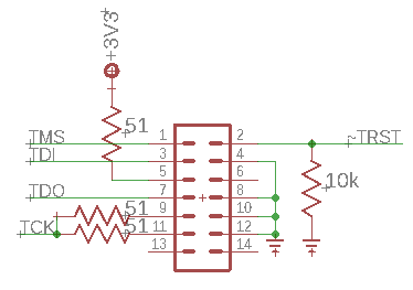
I am using CCSv8 and have my JTAG interface connected as shown below. Not sure if it's relevant or not, but my boot pins are configured for booting from SPI0 Flash using pull up/down resistors.

Any suggestions on how to approach this?

Thanks,

Matt

  • Matt,

    Your design looks ok - the resistors are in the same ballpark although a bit on the high side.
    software-dl.ti.com/.../emu_xds_target_connection_guide.html

    Since you have a good Test Connection, I would check the procedure below that will give you an idea of the status of the core via the ICEPICK. Check section 3 of the page below:
    processors.wiki.ti.com/.../GSG:Connecting_to_slave_cores_in_SoC_devices_v5

    This should give you insight if the core is in reset or powered down. Apart from this, the emulation circuitry does not have visibility over other subsystems of the device itself, thus requiring other methods to verify the reset and power rails.

    You could perhaps get a boundary scan probe and use the BSDL model (available for download at the device page) to try to verify this. Unfortunately neither CCS nor our Debug Probes support this JTAG mode.

    Some information about this can be found at the device's datasheet (section 6.30) and in some references on the internet such as:
    www.corelis.com/.../

    Hope this helps,
    Rafael
  • Hi Rafael,

    Thanks for your help. I tried checking the core status as you suggested and I'm not sure really sure what to make of it since it doesn't match any of the conditions listed on the page you linked. 

    Clock - CLK On

    Power - Power Off

    Clock Down Desired - CLK Down active

    Power Down Desired - Power Down inactive

    In Reset - In Reset

    Reset Control - Reset (None)

    I'm looking into trying to get a boundary scan probe as well if this doesn't get me anywhere.

    Thanks,

    Matt

  • Matt,

    Unfortunately it seems the core is receiving clock but it is not properly powered - the Power Off is an indicative of this diagnostic. At least you can tell the JTAG connection is ok, since you are able to reliably get data out of the ICEPICK router.

    I would check all power rails to the device - if your board has the PCB vias on each BGA pin, that can help determine if voltages are at least reaching the pads - although it does not tell anything about the quality of solder/connection.

    At this point you have a few options to inspect the status of the connection, but all of them require a third party probe and perhaps other equipment if you pursue the X-ray inspection route.

    An interesting presentation is shown below which talks about various inspection methods.
    nepp.nasa.gov/.../Dernning_BGAInspection.pdf

    Hope this helps,
    Rafael