This thread has been locked.

If you have a related question, please click the "Ask a related question" button in the top right corner. The newly created question will be automatically linked to this question.

CCS/CC2650: CC2650

Part Number: CC2650
Other Parts Discussed in Thread: SYSBIOS

Tool/software: Code Composer Studio

Hello.  

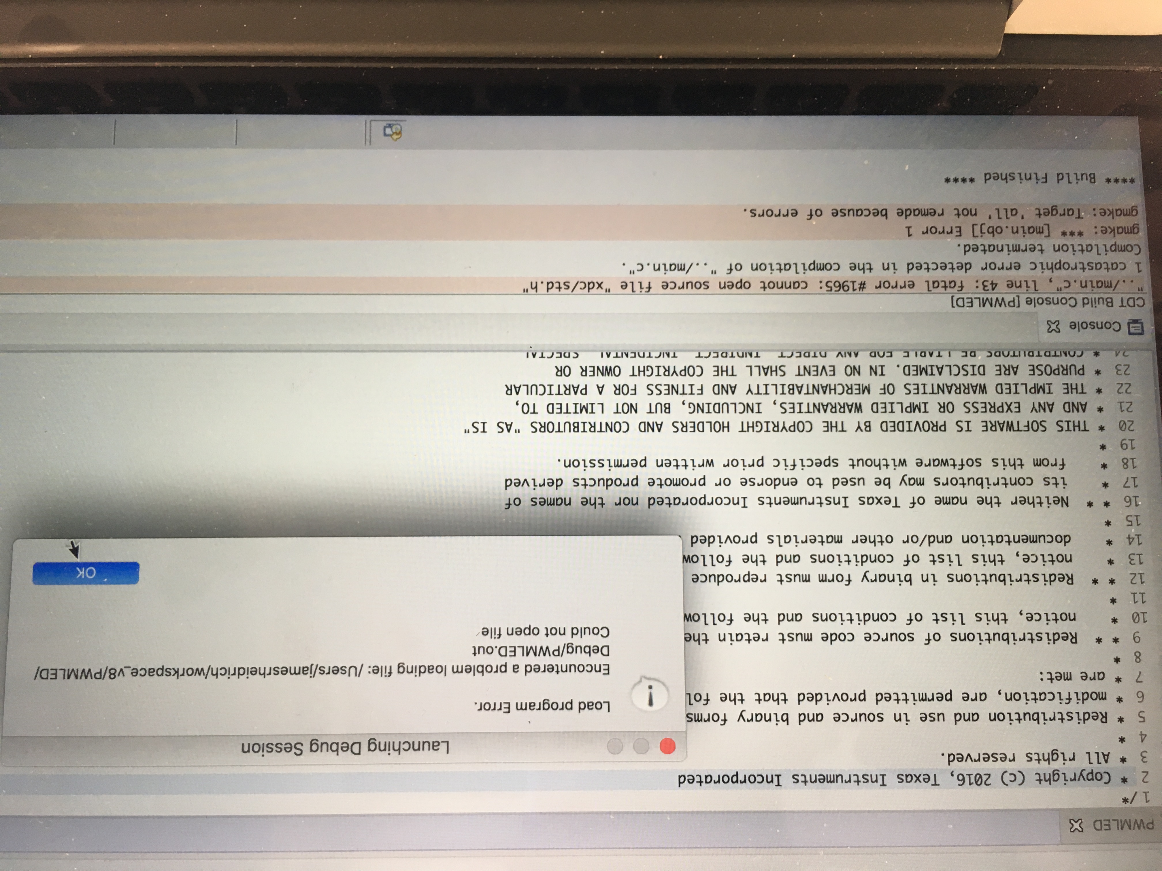
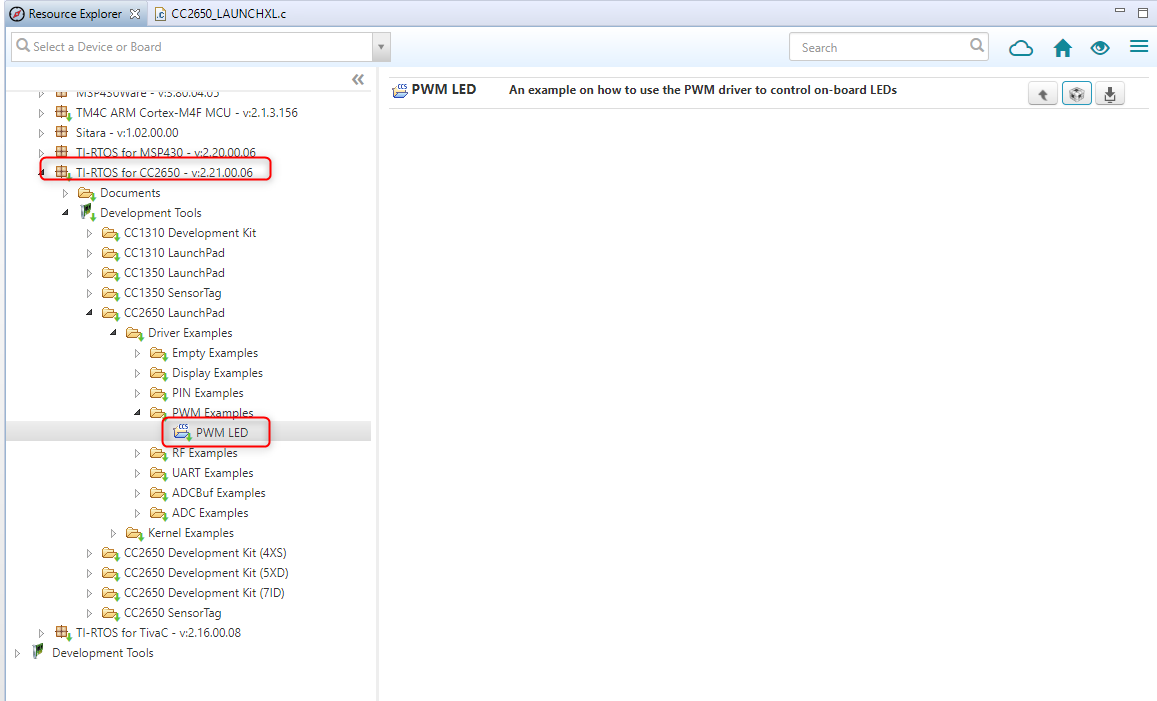
I am new to this platform and I am having difficulty running the PWMLED.  I am using a MacBook Pro to run CCS and I keep getting "Load program error. Encountered a problem loading file:/Users/jamesheidrich/workspace_v*/PWMLED/Debug/PWMLED.out Could not open file"  I've tried everything, but believe I am missing something simple.

Thanks,

Jim

  • Hi Jim,
    The most common cause of that error is that the project did not compile correctly and hence the debugger was unable to find the executable to load. Check your build output. Do you see any error messages in the build console?

    Thanks
    ki
  • Thanks for replying so quick.
    I didn't see an errors with build console. Is there a simpler project I could try? Thanks.
  • Does the file actually exist in the below path?

    /Users/jamesheidrich/workspace_v*/PWMLED/Debug/PWMLED.out

    If not, then something likely happened with the build. Can you provide all your build output in the build console? You can copy&paste to a text file and attach it to this thread.

    Thanks
    ki
  • /*
    * Copyright (c) 2016, Texas Instruments Incorporated
    * All rights reserved.
    *
    * Redistribution and use in source and binary forms, with or without
    * modification, are permitted provided that the following conditions
    * are met:
    *
    * * Redistributions of source code must retain the above copyright
    * notice, this list of conditions and the following disclaimer.
    *
    * * Redistributions in binary form must reproduce the above copyright
    * notice, this list of conditions and the following disclaimer in the
    * documentation and/or other materials provided with the distribution.
    *
    * * Neither the name of Texas Instruments Incorporated nor the names of
    * its contributors may be used to endorse or promote products derived
    * from this software without specific prior written permission.
    *
    * THIS SOFTWARE IS PROVIDED BY THE COPYRIGHT HOLDERS AND CONTRIBUTORS "AS IS"
    * AND ANY EXPRESS OR IMPLIED WARRANTIES, INCLUDING, BUT NOT LIMITED TO,
    * THE IMPLIED WARRANTIES OF MERCHANTABILITY AND FITNESS FOR A PARTICULAR
    * PURPOSE ARE DISCLAIMED. IN NO EVENT SHALL THE COPYRIGHT OWNER OR
    * CONTRIBUTORS BE LIABLE FOR ANY DIRECT, INDIRECT, INCIDENTAL, SPECIAL,
    * EXEMPLARY, OR CONSEQUENTIAL DAMAGES (INCLUDING, BUT NOT LIMITED TO,
    * PROCUREMENT OF SUBSTITUTE GOODS OR SERVICES; LOSS OF USE, DATA, OR PROFITS;
    * OR BUSINESS INTERRUPTION) HOWEVER CAUSED AND ON ANY THEORY OF LIABILITY,
    * WHETHER IN CONTRACT, STRICT LIABILITY, OR TORT (INCLUDING NEGLIGENCE OR
    * OTHERWISE) ARISING IN ANY WAY OUT OF THE USE OF THIS SOFTWARE,
    * EVEN IF ADVISED OF THE POSSIBILITY OF SUCH DAMAGE.
    */
    /*
    * ====================== CC2650_LAUNCHXL.c ===================================
    * This file is responsible for setting up the board specific items for the
    * CC2650 LaunchPad.
    */
    /*
    * ====================== Includes ============================================
    */
    #include <xdc/std.h>
    #include <xdc/runtime/System.h>
    #include <ti/sysbios/family/arm/m3/Hwi.h>
    #include <ti/drivers/PIN.h>
    #include <ti/drivers/pin/PINCC26XX.h>
    #include <ti/drivers/PWM.h>
    #include <ti/drivers/pwm/PWMTimerCC26XX.h>
    #include <ti/drivers/timer/GPTimerCC26XX.h>
    #include <ti/drivers/Power.h>
    #include <ti/drivers/power/PowerCC26XX.h>
    #include <inc/hw_memmap.h>
    #include <inc/hw_ints.h>
    #include <driverlib/ioc.h>
    #include <driverlib/udma.h>
    #include <Board.h>
    /*
    * ========================= IO driver initialization =========================
    * From main, PIN_init(BoardGpioInitTable) should be called to setup safe
    * settings for this board.
    * When a pin is allocated and then de-allocated, it will revert to the state
    * configured in this table.
    */
    /* Place into subsections to allow the TI linker to remove items properly */
    #if defined(__TI_COMPILER_VERSION__)
    #pragma DATA_SECTION(BoardGpioInitTable, ".const:BoardGpioInitTable")
    #pragma DATA_SECTION(PINCC26XX_hwAttrs, ".const:PINCC26XX_hwAttrs")
    #endif
    const PIN_Config BoardGpioInitTable[] = {
    Board_RLED | PIN_GPIO_OUTPUT_EN | PIN_GPIO_LOW | PIN_PUSHPULL | PIN_DRVSTR_MAX, /* LED initially off */
    Board_GLED | PIN_GPIO_OUTPUT_EN | PIN_GPIO_LOW | PIN_PUSHPULL | PIN_DRVSTR_MAX, /* LED initially off */
    Board_BTN1 | PIN_INPUT_EN | PIN_PULLUP | PIN_IRQ_BOTHEDGES | PIN_HYSTERESIS, /* Button is active low */
    Board_BTN2 | PIN_INPUT_EN | PIN_PULLUP | PIN_IRQ_BOTHEDGES | PIN_HYSTERESIS, /* Button is active low */
    Board_SPI_FLASH_CS | PIN_GPIO_OUTPUT_EN | PIN_GPIO_HIGH | PIN_PUSHPULL | PIN_DRVSTR_MIN, /* External flash chip select */
    Board_UART_RX | PIN_INPUT_EN | PIN_PULLDOWN, /* UART RX via debugger back channel */
    Board_UART_TX | PIN_GPIO_OUTPUT_EN | PIN_GPIO_HIGH | PIN_PUSHPULL, /* UART TX via debugger back channel */
    Board_SPI0_MOSI | PIN_INPUT_EN | PIN_PULLDOWN, /* SPI master out - slave in */
    Board_SPI0_MISO | PIN_INPUT_EN | PIN_PULLDOWN, /* SPI master in - slave out */
    Board_SPI0_CLK | PIN_INPUT_EN | PIN_PULLDOWN, /* SPI clock */
    PIN_TERMINATE
    };
    const PINCC26XX_HWAttrs PINCC26XX_hwAttrs = {
    .intPriority = ~0,
    .swiPriority = 0
    };
    /*============================================================================*/
    /*
    * ============================= Power begin ==================================
    */
    /* Place into subsections to allow the TI linker to remove items properly */
    #if defined(__TI_COMPILER_VERSION__)
    #pragma DATA_SECTION(PowerCC26XX_config, ".const:PowerCC26XX_config")
    #endif
    const PowerCC26XX_Config PowerCC26XX_config = {
    .policyInitFxn = NULL,
    .policyFxn = &PowerCC26XX_standbyPolicy,
    .calibrateFxn = &PowerCC26XX_calibrate,
    .enablePolicy = TRUE,
    .calibrateRCOSC_LF = TRUE,
    .calibrateRCOSC_HF = TRUE,
    };
    /*
    * ============================= Power end ====================================
    */
    /*
    * ============================= UART begin ===================================
    */
    /* Place into subsections to allow the TI linker to remove items properly */
    #if defined(__TI_COMPILER_VERSION__)
    #pragma DATA_SECTION(UART_config, ".const:UART_config")
    #pragma DATA_SECTION(uartCC26XXHWAttrs, ".const:uartCC26XXHWAttrs")
    #endif
    /* Include drivers */
    #include <ti/drivers/UART.h>
    #include <ti/drivers/uart/UARTCC26XX.h>
    /* UART objects */
    UARTCC26XX_Object uartCC26XXObjects[CC2650_LAUNCHXL_UARTCOUNT];
    unsigned char uartCC26XXRingBuffer[CC2650_LAUNCHXL_UARTCOUNT][32];
    /* UART hardware parameter structure, also used to assign UART pins */
    const UARTCC26XX_HWAttrsV2 uartCC26XXHWAttrs[CC2650_LAUNCHXL_UARTCOUNT] = {
    {
    .baseAddr = UART0_BASE,
    .powerMngrId = PowerCC26XX_PERIPH_UART0,
    .intNum = INT_UART0_COMB,
    .intPriority = ~0,
    .swiPriority = 0,
    .txPin = Board_UART_TX,
    .rxPin = Board_UART_RX,
    .ctsPin = PIN_UNASSIGNED,
    .rtsPin = PIN_UNASSIGNED,
    .ringBufPtr = uartCC26XXRingBuffer[0],
    .ringBufSize = sizeof(uartCC26XXRingBuffer[0])
    }
    };
    /* UART configuration structure */
    const UART_Config UART_config[] = {
    {
    .fxnTablePtr = &UARTCC26XX_fxnTable,
    .object = &uartCC26XXObjects[0],
    .hwAttrs = &uartCC26XXHWAttrs[0]
    },
    {NULL, NULL, NULL}
    };
    /*
    * ============================= UART end =====================================
    */
    /*
    * ============================= UDMA begin ===================================
    */
    /* Place into subsections to allow the TI linker to remove items properly */
    #if defined(__TI_COMPILER_VERSION__)
    #pragma DATA_SECTION(UDMACC26XX_config, ".const:UDMACC26XX_config")
    #pragma DATA_SECTION(udmaHWAttrs, ".const:udmaHWAttrs")
    #endif
    /* Include drivers */
    #include <ti/drivers/dma/UDMACC26XX.h>
    /* UDMA objects */
    UDMACC26XX_Object udmaObjects[CC2650_LAUNCHXL_UDMACOUNT];
    /* UDMA configuration structure */
    const UDMACC26XX_HWAttrs udmaHWAttrs[CC2650_LAUNCHXL_UDMACOUNT] = {
    {
    .baseAddr = UDMA0_BASE,
    .powerMngrId = PowerCC26XX_PERIPH_UDMA,
    .intNum = INT_DMA_ERR,
    .intPriority = ~0
    }
    };
    /* UDMA configuration structure */
    const UDMACC26XX_Config UDMACC26XX_config[] = {
    {
    .object = &udmaObjects[0],
    .hwAttrs = &udmaHWAttrs[0]
    },
    {NULL, NULL}
    };
    /*
    * ============================= UDMA end =====================================
    */
    /*
    * ========================== SPI DMA begin ===================================
    */
    /* Place into subsections to allow the TI linker to remove items properly */
    #if defined(__TI_COMPILER_VERSION__)
    #pragma DATA_SECTION(SPI_config, ".const:SPI_config")
    #pragma DATA_SECTION(spiCC26XXDMAHWAttrs, ".const:spiCC26XXDMAHWAttrs")
    #endif
    /* Include drivers */
    #include <ti/drivers/spi/SPICC26XXDMA.h>
    /* SPI objects */
    SPICC26XXDMA_Object spiCC26XXDMAObjects[CC2650_LAUNCHXL_SPICOUNT];
    /* SPI configuration structure, describing which pins are to be used */
    const SPICC26XXDMA_HWAttrsV1 spiCC26XXDMAHWAttrs[CC2650_LAUNCHXL_SPICOUNT] = {
    {
    .baseAddr = SSI0_BASE,
    .intNum = INT_SSI0_COMB,
    .intPriority = ~0,
    .swiPriority = 0,
    .powerMngrId = PowerCC26XX_PERIPH_SSI0,
    .defaultTxBufValue = 0,
    .rxChannelBitMask = 1<<UDMA_CHAN_SSI0_RX,
    .txChannelBitMask = 1<<UDMA_CHAN_SSI0_TX,
    .mosiPin = Board_SPI0_MOSI,
    .misoPin = Board_SPI0_MISO,
    .clkPin = Board_SPI0_CLK,
    .csnPin = Board_SPI0_CSN
    },
    {
    .baseAddr = SSI1_BASE,
    .intNum = INT_SSI1_COMB,
    .intPriority = ~0,
    .swiPriority = 0,
    .powerMngrId = PowerCC26XX_PERIPH_SSI1,
    .defaultTxBufValue = 0,
    .rxChannelBitMask = 1<<UDMA_CHAN_SSI1_RX,
    .txChannelBitMask = 1<<UDMA_CHAN_SSI1_TX,
    .mosiPin = Board_SPI1_MOSI,
    .misoPin = Board_SPI1_MISO,
    .clkPin = Board_SPI1_CLK,
    .csnPin = Board_SPI1_CSN
    }
    };
    /* SPI configuration structure */
    const SPI_Config SPI_config[] = {
    {
    .fxnTablePtr = &SPICC26XXDMA_fxnTable,
    .object = &spiCC26XXDMAObjects[0],
    .hwAttrs = &spiCC26XXDMAHWAttrs[0]
    },
    {
    .fxnTablePtr = &SPICC26XXDMA_fxnTable,
    .object = &spiCC26XXDMAObjects[1],
    .hwAttrs = &spiCC26XXDMAHWAttrs[1]
    },
    {NULL, NULL, NULL}
    };
    /*
    * ========================== SPI DMA end =====================================
    */
    /*
    * ============================= I2C Begin=====================================
    */
    /* Place into subsections to allow the TI linker to remove items properly */
    #if defined(__TI_COMPILER_VERSION__)
    #pragma DATA_SECTION(I2C_config, ".const:I2C_config")
    #pragma DATA_SECTION(i2cCC26xxHWAttrs, ".const:i2cCC26xxHWAttrs")
    #endif
    /* Include drivers */
    #include <ti/drivers/i2c/I2CCC26XX.h>
    /* I2C objects */
    I2CCC26XX_Object i2cCC26xxObjects[CC2650_LAUNCHXL_I2CCOUNT];
    /* I2C configuration structure, describing which pins are to be used */
    const I2CCC26XX_HWAttrsV1 i2cCC26xxHWAttrs[CC2650_LAUNCHXL_I2CCOUNT] = {
    {
    .baseAddr = I2C0_BASE,
    .powerMngrId = PowerCC26XX_PERIPH_I2C0,
    .intNum = INT_I2C_IRQ,
    .intPriority = ~0,
    .swiPriority = 0,
    .sdaPin = Board_I2C0_SDA0,
    .sclPin = Board_I2C0_SCL0,
    }
    };
    /* I2C configuration structure */
    const I2C_Config I2C_config[] = {
    {
    .fxnTablePtr = &I2CCC26XX_fxnTable,
    .object = &i2cCC26xxObjects[0],
    .hwAttrs = &i2cCC26xxHWAttrs[0]
    },
    {NULL, NULL, NULL}
    };
    /*
    * ========================== I2C end =========================================
    */
    /*
    * ========================== Crypto begin ====================================
    * NOTE: The Crypto implementation should be considered experimental
    * and not validated!
    */
    /* Place into subsections to allow the TI linker to remove items properly */
    #if defined(__TI_COMPILER_VERSION__)
    #pragma DATA_SECTION(CryptoCC26XX_config, ".const:CryptoCC26XX_config")
    #pragma DATA_SECTION(cryptoCC26XXHWAttrs, ".const:cryptoCC26XXHWAttrs")
    #endif
    /* Include drivers */
    #include <ti/drivers/crypto/CryptoCC26XX.h>
    /* Crypto objects */
    CryptoCC26XX_Object cryptoCC26XXObjects[CC2650_LAUNCHXL_CRYPTOCOUNT];
    /* Crypto configuration structure, describing which pins are to be used */
    const CryptoCC26XX_HWAttrs cryptoCC26XXHWAttrs[CC2650_LAUNCHXL_CRYPTOCOUNT] = {
    {
    .baseAddr = CRYPTO_BASE,
    .powerMngrId = PowerCC26XX_PERIPH_CRYPTO,
    .intNum = INT_CRYPTO_RESULT_AVAIL_IRQ,
    .intPriority = ~0,
    }
    };
    /* Crypto configuration structure */
    const CryptoCC26XX_Config CryptoCC26XX_config[] = {
    {
    .object = &cryptoCC26XXObjects[0],
    .hwAttrs = &cryptoCC26XXHWAttrs[0]
    },
    {NULL, NULL}
    };
    /*
    * ========================== Crypto end ======================================
    */
    /*
    * ========================= RF driver begin ==================================
    */
    /* Place into subsections to allow the TI linker to remove items properly */
    #if defined(__TI_COMPILER_VERSION__)
    #pragma DATA_SECTION(RFCC26XX_hwAttrs, ".const:RFCC26XX_hwAttrs")
    #endif
    /* Include drivers */
    #include <ti/drivers/rf/RF.h>
    /* RF hwi and swi priority */
    const RFCC26XX_HWAttrs RFCC26XX_hwAttrs = {
    .hwiCpe0Priority = ~0,
    .hwiHwPriority = ~0,
    .swiCpe0Priority = 0,
    .swiHwPriority = 0,
    };
    /*
    * ========================== RF driver end ===================================
    */
    /*
    * ========================= Display begin ====================================
    */
    /* Place into subsections to allow the TI linker to remove items properly */
    #if defined(__TI_COMPILER_VERSION__)
    #pragma DATA_SECTION(Display_config, ".const:Display_config")
    #pragma DATA_SECTION(displaySharpHWattrs, ".const:displaySharpHWattrs")
    #pragma DATA_SECTION(displayUartHWAttrs, ".const:displayUartHWAttrs")
    #endif
    #include <ti/mw/display/Display.h>
    #include <ti/mw/display/DisplaySharp.h>
    #include <ti/mw/display/DisplayUart.h>
    /* Structures for UartPlain Blocking */
    DisplayUart_Object displayUartObject;
    #ifndef BOARD_DISPLAY_UART_STRBUF_SIZE
    #define BOARD_DISPLAY_UART_STRBUF_SIZE 128
    #endif
    static char uartStringBuf[BOARD_DISPLAY_UART_STRBUF_SIZE];
    const DisplayUart_HWAttrs displayUartHWAttrs = {
    .uartIdx = Board_UART,
    .baudRate = 115200,
    .mutexTimeout = BIOS_WAIT_FOREVER,
    .strBuf = uartStringBuf,
    .strBufLen = BOARD_DISPLAY_UART_STRBUF_SIZE,
    };
    /* Structures for SHARP */
    DisplaySharp_Object displaySharpObject;
    #ifndef BOARD_DISPLAY_SHARP_SIZE
    #define BOARD_DISPLAY_SHARP_SIZE 96 // 96->96x96 is the most common board, alternative is 128->128x128.
    #endif
    static uint8_t sharpDisplayBuf[BOARD_DISPLAY_SHARP_SIZE * BOARD_DISPLAY_SHARP_SIZE / 8];
    const DisplaySharp_HWAttrs displaySharpHWattrs = {
    .spiIndex = Board_SPI0,
    .csPin = Board_LCD_CS,
    .extcominPin = Board_LCD_EXTCOMIN,
    .powerPin = Board_LCD_POWER,
    .enablePin = Board_LCD_ENABLE,
    .pixelWidth = BOARD_DISPLAY_SHARP_SIZE,
    .pixelHeight = BOARD_DISPLAY_SHARP_SIZE,
    .displayBuf = sharpDisplayBuf,
    };
    /* Array of displays */
    const Display_Config Display_config[] = {
    #if !defined(BOARD_DISPLAY_EXCLUDE_UART)
    {
    .fxnTablePtr = &DisplayUart_fxnTable,
    .object = &displayUartObject,
    .hwAttrs = &displayUartHWAttrs,
    },
    #endif
    #if !defined(BOARD_DISPLAY_EXCLUDE_LCD)
    {
    .fxnTablePtr = &DisplaySharp_fxnTable,
    .object = &displaySharpObject,
    .hwAttrs = &displaySharpHWattrs
    },
    #endif
    { NULL, NULL, NULL } // Terminator
    };
    /*
    * ========================= Display end ======================================
    */
    /*
    * ============================ GPTimer begin =================================
    * Remove unused entries to reduce flash usage both in Board.c and Board.h
    */
    /* Place into subsections to allow the TI linker to remove items properly */
    #if defined(__TI_COMPILER_VERSION__)
    #pragma DATA_SECTION(GPTimerCC26XX_config, ".const:GPTimerCC26XX_config")
    #pragma DATA_SECTION(gptimerCC26xxHWAttrs, ".const:gptimerCC26xxHWAttrs")
    #endif
    /* GPTimer hardware attributes, one per timer part (Timer 0A, 0B, 1A, 1B..) */
    const GPTimerCC26XX_HWAttrs gptimerCC26xxHWAttrs[CC2650_LAUNCHXL_GPTIMERPARTSCOUNT] = {
    { .baseAddr = GPT0_BASE, .intNum = INT_GPT0A, .intPriority = (~0), .powerMngrId = PowerCC26XX_PERIPH_GPT0, .pinMux = GPT_PIN_0A, },
    { .baseAddr = GPT0_BASE, .intNum = INT_GPT0B, .intPriority = (~0), .powerMngrId = PowerCC26XX_PERIPH_GPT0, .pinMux = GPT_PIN_0B, },
    { .baseAddr = GPT1_BASE, .intNum = INT_GPT1A, .intPriority = (~0), .powerMngrId = PowerCC26XX_PERIPH_GPT1, .pinMux = GPT_PIN_1A, },
    { .baseAddr = GPT1_BASE, .intNum = INT_GPT1B, .intPriority = (~0), .powerMngrId = PowerCC26XX_PERIPH_GPT1, .pinMux = GPT_PIN_1B, },
    { .baseAddr = GPT2_BASE, .intNum = INT_GPT2A, .intPriority = (~0), .powerMngrId = PowerCC26XX_PERIPH_GPT2, .pinMux = GPT_PIN_2A, },
    { .baseAddr = GPT2_BASE, .intNum = INT_GPT2B, .intPriority = (~0), .powerMngrId = PowerCC26XX_PERIPH_GPT2, .pinMux = GPT_PIN_2B, },
    { .baseAddr = GPT3_BASE, .intNum = INT_GPT3A, .intPriority = (~0), .powerMngrId = PowerCC26XX_PERIPH_GPT3, .pinMux = GPT_PIN_3A, },
    { .baseAddr = GPT3_BASE, .intNum = INT_GPT3B, .intPriority = (~0), .powerMngrId = PowerCC26XX_PERIPH_GPT3, .pinMux = GPT_PIN_3B, },
    };
    /* GPTimer objects, one per full-width timer (A+B) (Timer 0, Timer 1..) */
    GPTimerCC26XX_Object gptimerCC26XXObjects[CC2650_LAUNCHXL_GPTIMERCOUNT];

    /* GPTimer configuration (used as GPTimer_Handle by driver and application) */
    const GPTimerCC26XX_Config GPTimerCC26XX_config[CC2650_LAUNCHXL_GPTIMERPARTSCOUNT] = {
    { &gptimerCC26XXObjects[0], &gptimerCC26xxHWAttrs[0], GPT_A },
    { &gptimerCC26XXObjects[0], &gptimerCC26xxHWAttrs[1], GPT_B },
    { &gptimerCC26XXObjects[1], &gptimerCC26xxHWAttrs[2], GPT_A },
    { &gptimerCC26XXObjects[1], &gptimerCC26xxHWAttrs[3], GPT_B },
    { &gptimerCC26XXObjects[2], &gptimerCC26xxHWAttrs[4], GPT_A },
    { &gptimerCC26XXObjects[2], &gptimerCC26xxHWAttrs[5], GPT_B },
    { &gptimerCC26XXObjects[3], &gptimerCC26xxHWAttrs[6], GPT_A },
    { &gptimerCC26XXObjects[3], &gptimerCC26xxHWAttrs[7], GPT_B },
    };
    /*
    * ============================ GPTimer end ===================================
    */
    /*
    * ============================= PWM begin ====================================
    * Remove unused entries to reduce flash usage both in Board.c and Board.h
    */
    /* Place into subsections to allow the TI linker to remove items properly */
    #if defined(__TI_COMPILER_VERSION__)
    #pragma DATA_SECTION(PWM_config, ".const:PWM_config")
    #pragma DATA_SECTION(pwmtimerCC26xxHWAttrs, ".const:pwmtimerCC26xxHWAttrs")
    #endif
    /* PWM configuration, one per PWM output. */
    PWMTimerCC26XX_HwAttrs pwmtimerCC26xxHWAttrs[CC2650_LAUNCHXL_PWMCOUNT] = {
    { .pwmPin = Board_PWMPIN0, .gpTimerUnit = Board_GPTIMER0A },
    { .pwmPin = Board_PWMPIN1, .gpTimerUnit = Board_GPTIMER0B },
    { .pwmPin = Board_PWMPIN2, .gpTimerUnit = Board_GPTIMER1A },
    { .pwmPin = Board_PWMPIN3, .gpTimerUnit = Board_GPTIMER1B },
    { .pwmPin = Board_PWMPIN4, .gpTimerUnit = Board_GPTIMER2A },
    { .pwmPin = Board_PWMPIN5, .gpTimerUnit = Board_GPTIMER2B },
    { .pwmPin = Board_PWMPIN6, .gpTimerUnit = Board_GPTIMER3A },
    { .pwmPin = Board_PWMPIN7, .gpTimerUnit = Board_GPTIMER3B },
    };
    /* PWM object, one per PWM output */
    PWMTimerCC26XX_Object pwmtimerCC26xxObjects[CC2650_LAUNCHXL_PWMCOUNT];
    extern const PWM_FxnTable PWMTimerCC26XX_fxnTable;
    /* PWM configuration (used as PWM_Handle by driver and application) */
    const PWM_Config PWM_config[CC2650_LAUNCHXL_PWMCOUNT + 1] = {
    { &PWMTimerCC26XX_fxnTable, &pwmtimerCC26xxObjects[0], &pwmtimerCC26xxHWAttrs[0] },
    { &PWMTimerCC26XX_fxnTable, &pwmtimerCC26xxObjects[1], &pwmtimerCC26xxHWAttrs[1] },
    { &PWMTimerCC26XX_fxnTable, &pwmtimerCC26xxObjects[2], &pwmtimerCC26xxHWAttrs[2] },
    { &PWMTimerCC26XX_fxnTable, &pwmtimerCC26xxObjects[3], &pwmtimerCC26xxHWAttrs[3] },
    { &PWMTimerCC26XX_fxnTable, &pwmtimerCC26xxObjects[4], &pwmtimerCC26xxHWAttrs[4] },
    { &PWMTimerCC26XX_fxnTable, &pwmtimerCC26xxObjects[5], &pwmtimerCC26xxHWAttrs[5] },
    { &PWMTimerCC26XX_fxnTable, &pwmtimerCC26xxObjects[6], &pwmtimerCC26xxHWAttrs[6] },
    { &PWMTimerCC26XX_fxnTable, &pwmtimerCC26xxObjects[7], &pwmtimerCC26xxHWAttrs[7] },
    { NULL, NULL, NULL }
    };
    /*
    * ============================= PWM end ======================================
    */
    /*
    * ========================== ADCBuf begin =========================================
    */
    /* Place into subsections to allow the TI linker to remove items properly */
    #if defined(__TI_COMPILER_VERSION__)
    #pragma DATA_SECTION(ADCBuf_config, ".const:ADCBuf_config")
    #pragma DATA_SECTION(adcBufCC26xxHWAttrs, ".const:adcBufCC26xxHWAttrs")
    #pragma DATA_SECTION(ADCBufCC26XX_adcChannelLut, ".const:ADCBufCC26XX_adcChannelLut")
    #endif
    /* Include drivers */
    #include <ti/drivers/ADCBuf.h>
    #include <ti/drivers/adcbuf/ADCBufCC26XX.h>
    /* ADCBuf objects */
    ADCBufCC26XX_Object adcBufCC26xxObjects[CC2650_LAUNCHXL_ADCBufCOUNT];
    /*
    * This table converts a virtual adc channel into a dio and internal analogue input signal.
    * This table is necessary for the functioning of the adcBuf driver.
    * Comment out unused entries to save flash.
    * Dio and internal signal pairs are hardwired. Do not remap them in the table. You may reorder entire entries though.
    * The mapping of dio and internal signals is package dependent.
    */
    const ADCBufCC26XX_AdcChannelLutEntry ADCBufCC26XX_adcChannelLut[] = {
    {PIN_UNASSIGNED, ADC_COMPB_IN_VDDS},
    {PIN_UNASSIGNED, ADC_COMPB_IN_DCOUPL},
    {PIN_UNASSIGNED, ADC_COMPB_IN_VSS},
    {Board_DIO23_ANALOG, ADC_COMPB_IN_AUXIO7},
    {Board_DIO24_ANALOG, ADC_COMPB_IN_AUXIO6},
    {Board_DIO25_ANALOG, ADC_COMPB_IN_AUXIO5},
    {Board_DIO26_ANALOG, ADC_COMPB_IN_AUXIO4},
    {Board_DIO27_ANALOG, ADC_COMPB_IN_AUXIO3},
    {Board_DIO28_ANALOG, ADC_COMPB_IN_AUXIO2},
    {Board_DIO29_ANALOG, ADC_COMPB_IN_AUXIO1},
    {Board_DIO30_ANALOG, ADC_COMPB_IN_AUXIO0},
    };
    const ADCBufCC26XX_HWAttrs adcBufCC26xxHWAttrs[CC2650_LAUNCHXL_ADCBufCOUNT] = {
    {
    .intPriority = ~0,
    .swiPriority = 0,
    .adcChannelLut = ADCBufCC26XX_adcChannelLut,
    .gpTimerUnit = Board_GPTIMER0A,
    .gptDMAChannelMask = 1 << UDMA_CHAN_TIMER0_A,
    }
    };
    const ADCBuf_Config ADCBuf_config[] = {
    {&ADCBufCC26XX_fxnTable, &adcBufCC26xxObjects[0], &adcBufCC26xxHWAttrs[0]},
    {NULL, NULL, NULL},
    };
    /*
    * ========================== ADCBuf end =========================================
    */
    /*
    * ========================== ADC begin =========================================
    */
    /* Place into subsections to allow the TI linker to remove items properly */
    #if defined(__TI_COMPILER_VERSION__)
    #pragma DATA_SECTION(ADC_config, ".const:ADC_config")
    #pragma DATA_SECTION(adcCC26xxHWAttrs, ".const:adcCC26xxHWAttrs")
    #endif
    /* Include drivers */
    #include <ti/drivers/ADC.h>
    #include <ti/drivers/adc/ADCCC26XX.h>
    /* ADC objects */
    ADCCC26XX_Object adcCC26xxObjects[CC2650_LAUNCHXL_ADCCOUNT];
    const ADCCC26XX_HWAttrs adcCC26xxHWAttrs[CC2650_LAUNCHXL_ADCCOUNT] = {
    {
    .adcDIO = Board_DIO23_ANALOG,
    .adcCompBInput = ADC_COMPB_IN_AUXIO7,
    .refSource = ADCCC26XX_FIXED_REFERENCE,
    .samplingDuration = ADCCC26XX_SAMPLING_DURATION_2P7_US,
    .inputScalingEnabled = true,
    .triggerSource = ADCCC26XX_TRIGGER_MANUAL
    },
    {
    .adcDIO = Board_DIO24_ANALOG,
    .adcCompBInput = ADC_COMPB_IN_AUXIO6,
    .refSource = ADCCC26XX_FIXED_REFERENCE,
    .samplingDuration = ADCCC26XX_SAMPLING_DURATION_2P7_US,
    .inputScalingEnabled = true,
    .triggerSource = ADCCC26XX_TRIGGER_MANUAL
    },
    {
    .adcDIO = Board_DIO25_ANALOG,
    .adcCompBInput = ADC_COMPB_IN_AUXIO5,
    .refSource = ADCCC26XX_FIXED_REFERENCE,
    .samplingDuration = ADCCC26XX_SAMPLING_DURATION_2P7_US,
    .inputScalingEnabled = true,
    .triggerSource = ADCCC26XX_TRIGGER_MANUAL
    },
    {
    .adcDIO = Board_DIO26_ANALOG,
    .adcCompBInput = ADC_COMPB_IN_AUXIO4,
    .refSource = ADCCC26XX_FIXED_REFERENCE,
    .samplingDuration = ADCCC26XX_SAMPLING_DURATION_2P7_US,
    .inputScalingEnabled = true,
    .triggerSource = ADCCC26XX_TRIGGER_MANUAL
    },
    {
    .adcDIO = Board_DIO27_ANALOG,
    .adcCompBInput = ADC_COMPB_IN_AUXIO3,
    .refSource = ADCCC26XX_FIXED_REFERENCE,
    .samplingDuration = ADCCC26XX_SAMPLING_DURATION_2P7_US,
    .inputScalingEnabled = true,
    .triggerSource = ADCCC26XX_TRIGGER_MANUAL
    },
    {
    .adcDIO = Board_DIO28_ANALOG,
    .adcCompBInput = ADC_COMPB_IN_AUXIO2,
    .refSource = ADCCC26XX_FIXED_REFERENCE,
    .samplingDuration = ADCCC26XX_SAMPLING_DURATION_2P7_US,
    .inputScalingEnabled = true,
    .triggerSource = ADCCC26XX_TRIGGER_MANUAL
    },
    {
    .adcDIO = Board_DIO29_ANALOG,
    .adcCompBInput = ADC_COMPB_IN_AUXIO1,
    .refSource = ADCCC26XX_FIXED_REFERENCE,
    .samplingDuration = ADCCC26XX_SAMPLING_DURATION_2P7_US,
    .inputScalingEnabled = true,
    .triggerSource = ADCCC26XX_TRIGGER_MANUAL
    },
    {
    .adcDIO = Board_DIO30_ANALOG,
    .adcCompBInput = ADC_COMPB_IN_AUXIO0,
    .refSource = ADCCC26XX_FIXED_REFERENCE,
    .samplingDuration = ADCCC26XX_SAMPLING_DURATION_10P9_MS,
    .inputScalingEnabled = true,
    .triggerSource = ADCCC26XX_TRIGGER_MANUAL
    },
    {
    .adcDIO = PIN_UNASSIGNED,
    .adcCompBInput = ADC_COMPB_IN_DCOUPL,
    .refSource = ADCCC26XX_FIXED_REFERENCE,
    .samplingDuration = ADCCC26XX_SAMPLING_DURATION_2P7_US,
    .inputScalingEnabled = true,
    .triggerSource = ADCCC26XX_TRIGGER_MANUAL
    },
    {
    .adcDIO = PIN_UNASSIGNED,
    .adcCompBInput = ADC_COMPB_IN_VSS,
    .refSource = ADCCC26XX_FIXED_REFERENCE,
    .samplingDuration = ADCCC26XX_SAMPLING_DURATION_2P7_US,
    .inputScalingEnabled = true,
    .triggerSource = ADCCC26XX_TRIGGER_MANUAL
    },
    {
    .adcDIO = PIN_UNASSIGNED,
    .adcCompBInput = ADC_COMPB_IN_VDDS,
    .refSource = ADCCC26XX_FIXED_REFERENCE,
    .samplingDuration = ADCCC26XX_SAMPLING_DURATION_2P7_US,
    .inputScalingEnabled = true,
    .triggerSource = ADCCC26XX_TRIGGER_MANUAL
    }
    };
    const ADC_Config ADC_config[] = {
    {&ADCCC26XX_fxnTable, &adcCC26xxObjects[0], &adcCC26xxHWAttrs[0]},
    {&ADCCC26XX_fxnTable, &adcCC26xxObjects[1], &adcCC26xxHWAttrs[1]},
    {&ADCCC26XX_fxnTable, &adcCC26xxObjects[2], &adcCC26xxHWAttrs[2]},
    {&ADCCC26XX_fxnTable, &adcCC26xxObjects[3], &adcCC26xxHWAttrs[3]},
    {&ADCCC26XX_fxnTable, &adcCC26xxObjects[4], &adcCC26xxHWAttrs[4]},
    {&ADCCC26XX_fxnTable, &adcCC26xxObjects[5], &adcCC26xxHWAttrs[5]},
    {&ADCCC26XX_fxnTable, &adcCC26xxObjects[6], &adcCC26xxHWAttrs[6]},
    {&ADCCC26XX_fxnTable, &adcCC26xxObjects[7], &adcCC26xxHWAttrs[7]},
    {&ADCCC26XX_fxnTable, &adcCC26xxObjects[8], &adcCC26xxHWAttrs[8]},
    {&ADCCC26XX_fxnTable, &adcCC26xxObjects[9], &adcCC26xxHWAttrs[9]},
    {&ADCCC26XX_fxnTable, &adcCC26xxObjects[10], &adcCC26xxHWAttrs[10]},
    {NULL, NULL, NULL},
    };
    /*
    * ========================== ADC end =========================================
    */
    /*
    * =============================== Watchdog ===============================
    */
    /* Place into subsections to allow the TI linker to remove items properly */
    #if defined(__TI_COMPILER_VERSION__)
    #pragma DATA_SECTION(Watchdog_config, ".const:Watchdog_config")
    #pragma DATA_SECTION(watchdogCC26XXHWAttrs, ".const:watchdogCC26XXHWAttrs")
    #endif
    #include <ti/drivers/Watchdog.h>
    #include <ti/drivers/watchdog/WatchdogCC26XX.h>
    WatchdogCC26XX_Object watchdogCC26XXObjects[CC2650_LAUNCHXL_WATCHDOGCOUNT];
    const WatchdogCC26XX_HWAttrs watchdogCC26XXHWAttrs[CC2650_LAUNCHXL_WATCHDOGCOUNT] = {
    {
    .baseAddr = WDT_BASE,
    .intNum = INT_WDT_IRQ,
    .reloadValue = 1000 /* Reload value in milliseconds */
    },
    };
    const Watchdog_Config Watchdog_config[] = {
    {
    .fxnTablePtr = &WatchdogCC26XX_fxnTable,
    .object = &watchdogCC26XXObjects[0],
    .hwAttrs = &watchdogCC26XXHWAttrs[0]
    },
    {NULL, NULL, NULL},
    };
    /*
    * ======== CC26XX_LAUNCHXL_initWatchdog ========
    */
    void CC26XX_LAUNCHXL_initWatchdog(void)
    {
    Watchdog_init();
    }

  • That is the source file but I am looking for the build output in the build console.

    The build console looks like the image below:

    Please copy and paste all the ouput there to a text file and attach it to this thread

    Thanks

    ki

  •   Sorry about that.

  • I was looking for the entire build output. But from the snippet there, it looks like an include path issue.

    I assume you are using the PWMLED example from TI-RTOS. How are you importing the example into your workspace?
  • You are correct. I saved the folder to my desktop and copied and pasted the file I wanted to run. I had issues with every .h and .c file giving me an error message. When I tried to import the folder with all the .h and .c files into CCS, the program wouldn't allow me.
  • I suggest importing the example from Resource Explorer. Can you give that a try?

    Thanks

    ki

  •   I was able to import and build the program without an error message, but got an error for Ti Cloud Agent Installation.  I downloaded and installed the software and refreshed the browser, but still had an issue loading. I selected Run with the PWMLED_CC2650_Launchxl_Ti.

  • The cloud agent issue is a different issue. But going back to the original issue, please use Resource Explorer inside CCS desktop and import/build the example from there
  • Its working, thanks for all your help.