This thread has been locked.

If you have a related question, please click the "Ask a related question" button in the top right corner. The newly created question will be automatically linked to this question.

CCS/AM5726: Implementation of XDS100v2 on Custom board

Part Number: AM5726

Tool/software: Code Composer Studio

Hi

We put XDS100v2 on our board, completely copied it from idk5728.

Copied eeprom from idk to our board. 

All JTAG signals : TDO, CLK, TDO, RST go back and forth, but we get "SC_ERR_CTL_CBL_BREAK_FAR"  when I click test on JTAG connection.

I'd like to compare traffic between JTAG/USB and usb software, but I do not know where to start looking.

Any idea would be appreciated.

BTW: 

Article  is outdated MProg and http://processors.wiki.ti.com/images/d/d9/XDS100v2.zip 

[Start: Texas Instruments XDS100v2 USB Debug Probe_0]

Execute the command:

%ccs_base%/common/uscif/dbgjtag -f %boarddatafile% -rv -o -F inform,logfile=yes -S pathlength -S integrity

[Result]


-----[Print the board config pathname(s)]------------------------------------

C:\Users\RASTY~1.SLU\AppData\Local\TEXASI~1\
CCS\ti\0\0\BrdDat\testBoard.dat

-----[Print the reset-command software log-file]-----------------------------

This utility has selected a 100- or 510-class product.
This utility will load the adapter 'jioserdesusb.dll'.
The library build date was 'Nov 6 2017'.
The library build time was '10:36:36'.
The library package version is '7.0.100.0'.
The library component version is '35.35.0.0'.
The controller does not use a programmable FPGA.
The controller has a version number of '4' (0x00000004).
The controller has an insertion length of '0' (0x00000000).
This utility will attempt to reset the controller.
This utility has successfully reset the controller.

-----[Print the reset-command hardware log-file]-----------------------------

The scan-path will be reset by toggling the JTAG TRST signal.
The controller is the FTDI FT2232 with USB interface.
The link from controller to target is direct (without cable).
The software is configured for FTDI FT2232 features.
The controller cannot monitor the value on the EMU[0] pin.
The controller cannot monitor the value on the EMU[1] pin.
The controller cannot control the timing on output pins.
The controller cannot control the timing on input pins.
The scan-path link-delay has been set to exactly '0' (0x0000).

-----[The log-file for the JTAG TCLK output generated from the PLL]----------

There is no hardware for programming the JTAG TCLK frequency.

-----[Measure the source and frequency of the final JTAG TCLKR input]--------

There is no hardware for measuring the JTAG TCLK frequency.

-----[Perform the standard path-length test on the JTAG IR and DR]-----------

This path-length test uses blocks of 64 32-bit words.

The JTAG IR instruction path-length was not recorded.

-----[Perform the Integrity scan-test on the JTAG IR]------------------------

This test will use blocks of 64 32-bit words.
This test will be applied just once.

Do a test using 0xFFFFFFFF.
Scan tests: 1, skipped: 0, failed: 0

-----[An error has occurred and this utility has aborted]--------------------

This error is generated by TI's USCIF driver or utilities.

The value is '-183' (0xffffff49).
The title is 'SC_ERR_CTL_CBL_BREAK_FAR'.

The explanation is:
The controller has detected a cable break far-from itself.
The user must connect the cable/pod to the target.

[End: Texas Instruments XDS100v2 USB Debug Probe_0]

  • Hi,

    I would first take a look at the suggestions at the following reference:

    software-dl.ti.com/.../ccs_debugging_jtag_connectivity_issues.html

    The section above also references our XDS Target Connection guide, which contains all design details for the JTAG circuit design.

    Hope this helps,
    Rafael
  • Hi

    Thank you very much for the answer.

    1. I cannot correlate between "pins" on standard JTAG and schematics. What is TVRef and TDIS on XDS100v2 ?

    2. I found original XDS100v2 schematics and compare it idk5728. Directions of TDI and TDO seems to be swapped.

    Please refer to the attached diagram (left original xds100v, right is idk5728 that we copied).

    Best regards

    Rasty

  • Hi,
    I'd appreciate a list of JTAG "pins" vs FTDI pins.

    Thanks
    Rasty
  • Rasty,

    There can be many reasons why you see emulation failure.  We need to break this issue into segments for debugging.  It appears that the USB connection is communicating to the FTDI chip.  It then reports lack of control and monitoring of the JTAG signals.  To verify that the FTDI chip is functioning correctly, I recommend that you disconnect the JTAG signals from the processor and test the emulator standalone.  You will need a pull-down resistor on the TRSTn pin, pull-up resistors on EMU[1:0] and a loop from TDO to TDI.  This should allow the JTAG scan test to function.

    Similarly, do you have a JTAG header implemented on the processor such that you can interact with the processor separate from the XDS100 on-board emulator?  You must make sure the processor is properly powered and out of reset for the JTAG scan test to be successful.  If the JTAG scan test fails using an external emulator connected directly to the processor, then the problem is not related to the XDS100v2 implemented in the FTDI chip.

    Since you copied the AM572x IDK design, I assume that you are familiar with the circuitry and operation of the IDK.  Do you have an AM572x IDK EVM?  Can you connect to it over the USB and XDS100v2 and successfully control the processor through CCS?

    Are you also familiar with the content in the AM572x IDK UG?  Known Issue A.10 discusses a limitation in this XDS100v2 implementation.  Per this document, you should have copied the XDS100v2 implementation from the AM571x IDK EVM if you wanted full voltage isolation between the emulator and the processor.

    How may prototypes have you assembled?  Do they all fail in the same manner?

    Tom

  • Hi Tom,
    We see CLK, TDI, TDO signals, but get error -183.
    There is contradicting information that I find on the Internet: some sources say that it is voltage sense while other (TI) mention incorrect TDI/TDO.
    We completely copied idk578x design and passed TI's audit.

    Please refer to my previous comment e2e.ti.com/.../2778879
    I'd like to get the answer to 2 questions
    1) FTDI pinout vs "standard" JTAG signals
    2) why signal directions that I see on XDS100v2 reference design (from TI website) differ from idk572x?

    Best regards
    Rasty
  • Rasty,

    Tom's line of diagnostics is quite reasonable - did you try the steps mentioned by him and performed the tests to try and isolate the issue?

    Regarding your questions:

    1) Signal descriptions and directions are shown at the XDS Target Connection Guide mentioned by me before:

    software-dl.ti.com/.../emu_xds_target_connection_guide.html

    2) The XDS100v2 reference design has a drawing error. The signal directions can be seen from the reference above.

    The reason you see some contradictory information on the web regarding error -183 is due to the fact the Debug Probe has limited visibility about the hardware status - in other words, it can be difficult to precisely determine the vast number of possible root causes for an issue simply by sensing the JTAG lines. That is why the differential diagnostics and, more importantly, a populated JTAG debug probe in your board are important to isolate the issue.

    Hope this helps,
    Rafael
  • Hi,
    I understand about drawing error.
    Unfortunately we cannot cross check "our" xds100 with idk, because it is implemented on PCB and it is physically impossible to make any cross check.
    We use external XDS200 and can control CPU over the same signals (TDI/TDO/TCLK/ etc) when onboard xdv100ve is not powered via USB. Only onboard impementation does not work.

    Where are "TVRef" and "TDIS" on xds100v2 or idk572x schematics?

    Thanks
    Rasty
  • Rasty,

    I did not ask you to cross-check the design with the AM572x IDK design.  I asked you to segment your board implementation so that we can debug the problem.  You can do this by removing U106 and U107 on your board.  You can then add the requested pull-up and pull-down resistors and a jumper looping TDI to TDO.  This should allow the JTAG emulator continuity test to succeed.  That will prove that everything is correct with the implementation of the XDS100v2 embedded emulator.

    I am glad to see that JTAG emulation using an external emulator is fully functional.  This is useful information.

    How may prototypes have you assembled?  Do they all fail in the same manner?

    Tom

  • Rasty,

    The signal directions are reversed at the IO pins of the FTDI chip.  TCK, TDI, TMS and TRSTn are outputs from the FTDI chip and TDO is an input to it.  Also, EMU[1:0] are outputs from the FTDI chip.  TDI is an input to the AM572x processor while TDO is an output from the AM572x processor.  This can be confirmed on the IDK schematic as well.

    Tom

  • Rasty,

    XDS100v2 does not have support for TVRef or TDIS.  These are supported in more feature-rich emulator implementations.  The XDS100v2 only has support for the 5 JTAG signals and the 2 EMU signals.

    Tom

  • Hi Tom

    We assembled 10+ boards, I checked 2 and both behave the same.

    We fully copied idk schematics and  see that TDI/TDO/CLK are alive. That is why I question schematics.and look for other signals like target voltage sense and similar.

    Since TI website contains reference to outdated FTDI tools,/files I copied (with FT_Prog) EEPROM from IDK and Burned it to our board. CCS recognized it as expected.

    I really appreciate your suggestion. Problem seems to be not complicated.

    Please post here troubleshooting guidelines, commands that I have to issue in order to check  basic TDI/TDO loopback.

    CPUID, etc and expected results. I'll check it by myself , compare it with IDK and updated you with results. 

    I'll try to check how we can do less intrusive diagnostic, without disassembly of circuits.

    Best regards

    Rasty

  • Rasty,

    Copying the EPROM image from the IDK to get the XDS100v2 programming is not the proper way to get an image for your design.  The proper solution is requesting approval and access to the EPK design collateral for the XDS100.  I will find the correct contact for this.

    You have already indicated that the JTAG connections from the emulation header to the AM5726 are correct and robust since you are able to use an external emulator to connect with CCS.  You believe that the FTDI chip is properly implemented since it appears to enumerate on the USB.  We need for you to implement the test loopback requested so that we can be sure of this.  There is nothing else to debug.  Once this loopback is enabled with the proper pull resistors attached, you should be able to connect with CCS and then execute a JTAG chain continuity test.  If the FTDI is working as expected, this should pass all tests and report a scan length of zero.

    Tom

  • Hi Tom,

    How do I get proper eeprom for FT2232HL?

    How do I  execute "a JTAG chain continuity test"?

    I see only "pathlength", "brokenpath" and "integrity"

    When I run "dbgjtag.exe -f testBoard.dat -rv -Sbrokenpath" and get following picture.

    Please notice that jtag_tdo_after_buffer is measured on pin 18 of FT2232HL

    What do I lean from it?

    I also attach signal capture, you can open it with DigiView www.tech-tools.com/.../digiview-930.exe

    https://e2e.ti.com/cfs-file/__key/communityserver-discussions-components-files/81/maxx_2D00_jtag.7z

    Thanks

    Rasty

  • Rasty,

    Please see the XDS100 Wiki for detailed instructions for implementing the on-board emulator and for the official method to obtain an EEPROM image.

    Tom

  • Rasty,

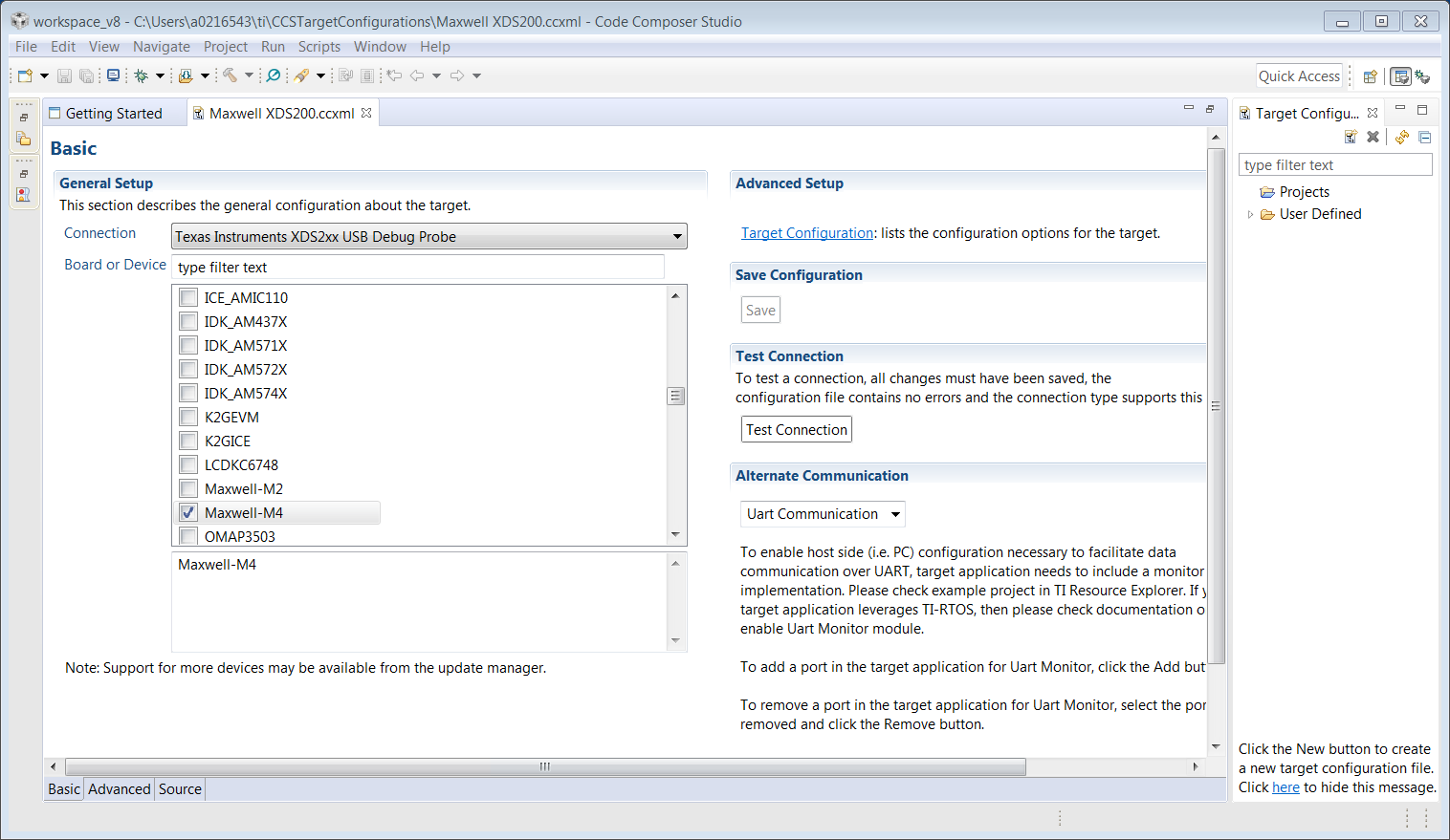
    I use CCS to preform continuity tests.  I believe it is using dbgjtag within the GUI since it has text results similar to what you posted.  This is available on the emulator selection page within CCS.  See below:

    Tom

  • Rasty,

    I see that the dbgjtag wiki has been replaced with the following web document that deals with this topic in-depth:

    Tom

  • Rasty,

    I have suggested that you implement a TDO-TDI loopback after the FTDI chip.  Is that what you are showing in the capture above?  What output from the scan test did you get when you ran the loopback test?

    Tom

  • Hi Tom,


    1. I took contents of eeprom from software-dl.ti.com/.../XDS100v2Schematic(rev2)-Setup.zip
    It uses outdated software, but I managed to download and run it,
    2. I did short circuit on TDI/TDO and got the same result as I posted earlier, TDI/TDO look indentical (of course) on logic analyzer
    3. Article that you refer to (software-dl.ti.com/.../ccsv7_debugging_jtag_connectivity_issues.html) mentions TVRef/TDIS - "Another possible cause of a "cable break far-from itself" could be that the TVRef signal (pin 5) is pulled up to the IO voltage, or TDIS (pin 4) is pulled-down to ground. TVRef should be connected to the IO voltage through a small current limiting resistor. TDIS should be connected directly to ground"

    But both do not exist in XDS100v2 as you wrote earlier.

    I start thinking that something wrong with FTDI configuration or TVRef/TDIS do exist.
    I need some low level command to send and receive training sequence via JTAG.

    Thanks
    Rasty
  • Rasty,

    I cannot verify TVRef and TDIS connections from the schematic snippet attached above.  Do you have pin 32 of the FTDI chip connected to ground?  Do you have pin 28 of the FTDI chip connected to 3.3V?  Are your JTAG IO voltages all 3.3V signalling like on the IDK?

    Tom

  • Rasty,

    Also, what about PWREN# on pin 60?  Is it connected to the VBUS voltage through an LED and resistor as shown?

    Tom

  • Hi Tom,

    Problem was missing pulldown on ACBUS5. What is it?

    Is it possible to get most updated design of xds100v2 with all the pins and their functions, eeprom and software?

    I'd also like to know where we connect RTCLK to FDTI and enable adaptive clocking.

    Thanks

    Rasty

  • Rasty,

    From the error message and the required connection to ground, I believe this is TDIS.

    The most updated information is on the XDS100 wiki page provided and the link to the schematics from the link below copied from that page:

    software-dl.ti.com/.../xds100v3_v2.0.zip

    There is no connection for RTCLK in XDS100.  A higher performance emulation circuit would be needed for that such as XDS200.

    Tom