This thread has been locked.

If you have a related question, please click the "Ask a related question" button in the top right corner. The newly created question will be automatically linked to this question.

CCS/DRV8301-HC-C2-KIT: Motor spinning wrong (Firmware parameters settings)

Part Number: DRV8301-HC-C2-KIT
Other Parts Discussed in Thread: MOTORWARE

Tool/software: Code Composer Studio

Hello, how are you? I need your help because we are having problems trying to spin a motor correctly.

This is our configuration:

  • Eval. Board: DRV8301-HC-EVM Rev D

  • Embedded Board: TMDSCNCD28069MISO

  • Motor: PMSM type, 7 pairs of poles, 700 kV

  • Power Supply: 12V

We have set the user.h file according to the information provided by the InstaSPIN Projects and Labs User’s Guide, the "motorware_selecting_user_variables" spreadsheet and the comments found in the firmware. But there we found some contradictory data and we have several doubts.

Specifically, the issue is that the motor can not spin as fast as we need (more than 6 krpm) because the IDE crashes. And by using another set of parameters, the issue is that there is no relationship between the set speed and the actual speed. Here I attach both user.h files (user_R & user_L).

Thank you very much.

Regards,

Luciano


user_R.h

user_L.h

  • Hi Luciano

    If you are using one of our EVMs, then you shouldn't need to change certain things in the user.h such as USER_ADC_FULL_SCALE_VOLTAGE_V, USER_ADC_FULL_SCALE_CURRENT_A, and USER_VOLTAGE_FILTER_POLE_Hz. These parameters are based on the hardware, and unless you've made physical changes to the EVM, they should have been calculated and populated in the user.h with the distribution of Motorware.

    Can you please try resetting these to the default values?

    It also appears that your motor has a very low identified inductance - did you use lab2c to identify your motor? You may want to rerun ID with that lab, which is specifically intended for low inductance identification. An incorrectly identified set of parameters can lead to inaccuracy of the speed feedback

    Sean
  • Hi Sean, thank you very much for your response and for your help.

    Yes, I am using one of your EVMs (DRV8301-HC-EVM Rev D). So I tried resetting those parameters to the default values and repeated lab2c, but in this case, the motor didn't sping well and identification was not completed successfully.

    The only way that we discover that we can make that lab work, was by modifying the "USER_ADC_FULL_SCALE_CURRENT_A" value. Instead of using its default value (82.5), we used values such as 30.0 or 40.0. It was the only thing that made lab2c work fine and the motor spins.

    Here I attach the new user.h file. Do you have any idea what it could be wrong with our configuration?


    Best regards,
    Luciano

    user1219.h

  • What is the rated current and rated frequency of your motor?

    Sean
  • - Rated current: We don't know it, but we ran the motor using an off-the-shelf ESC and it can handle 40A continuous.

    - Rated frequency: 1,062 Hz
    We have calculated it using this formula:
    Rated frequency = Maximum Target RPM * Pole Pairs / 60 = 9,100 * 7 / 60 = 1,062

    Regards,
    Luciano
  • The rated current and frequency should be parameters of the motor itself. Do you have access to the datasheet or is there some faceplate/nameplate info for this motor?

    Sean
  • Hi Sean. I contacted the motor manufacturer and he sent me these motor parameter specification:

    • Brushless
    • 700kV
    • 7 pairs of poles
    • 8,400 RPM (@12V)
    • 980Hz (@12V)
    • 800W
    • 45A (Continuous Current)
    • 65A (Max. Burst Current)

    Is this enough?

    Luciano

  • You shouldn't change the USER_ADC_FULL_SCALE_CURRENT_A as Sean mentioned since you didn't change anything on the h/w board.

    You might increase USER_MOTOR_MAX_CURRENT to 60A, USER_MOTOR_RES_EST_CURRENT to 5A, even higher, USER_MOTOR_IND_EST_CURRENT to -5A, and USER_MOTOR_FLUX_EST_FREQ_Hz to 40Hz, and try lab02c again. Please make sure there is no load to the motor during identification.

    If it's possible, please post some current waveforms to show the failed state. Actually, the EVM kit can't support your motor to be run under full or heavy load limit to the maximum scale current of the EVM kit is not enough, just for identification or under a low light load.
  • Hello Yanming, thank you very much for your response. We follow all your suggestions and this was the result:

    In lab02c, we couldn’t increase the USER_MOTOR_MAX_CURRENT to 60A because we can't get the program to run if it is higher than the USER_IQ_FULL_SCALE_CURRENT_A (41.25A). So we had to reduce it to 40A.

    Then, when we set USER_MOTOR_FLUX_EST_FREQ_Hz to 40Hz, the motor didn’t run smoothly throughout the entire test. The only way to achieve this goal was to increase it to 80 Hz.

    With these values, we were able to turn the motor and successfully complete lab02c without interruptions. See the attached user.h file.

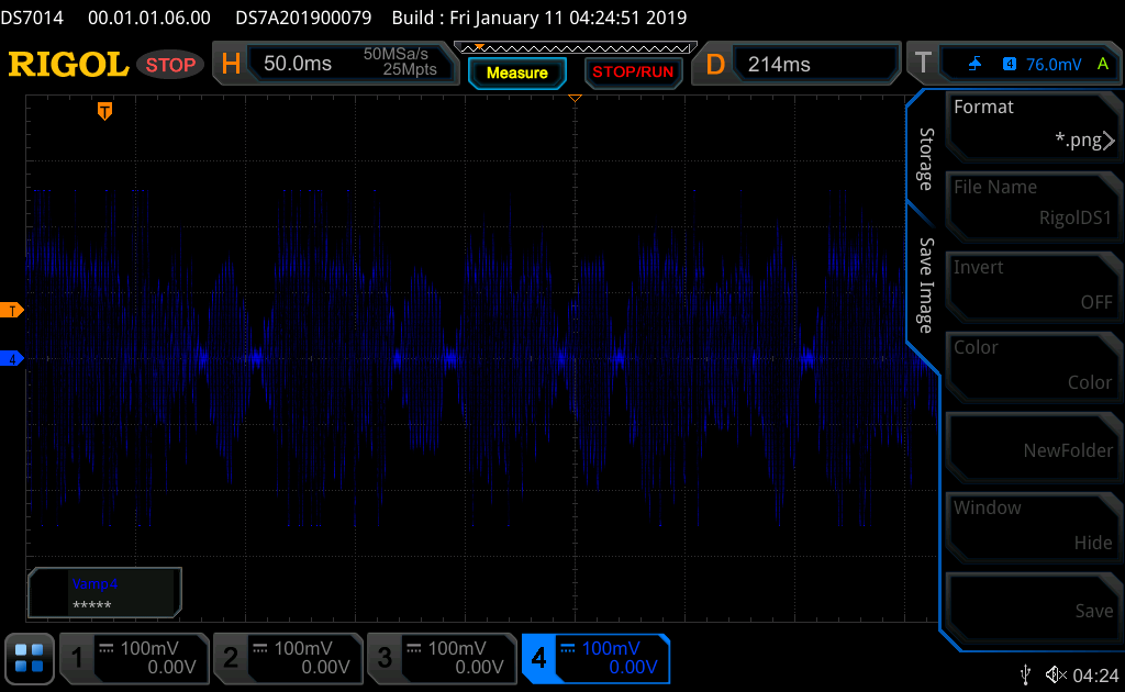
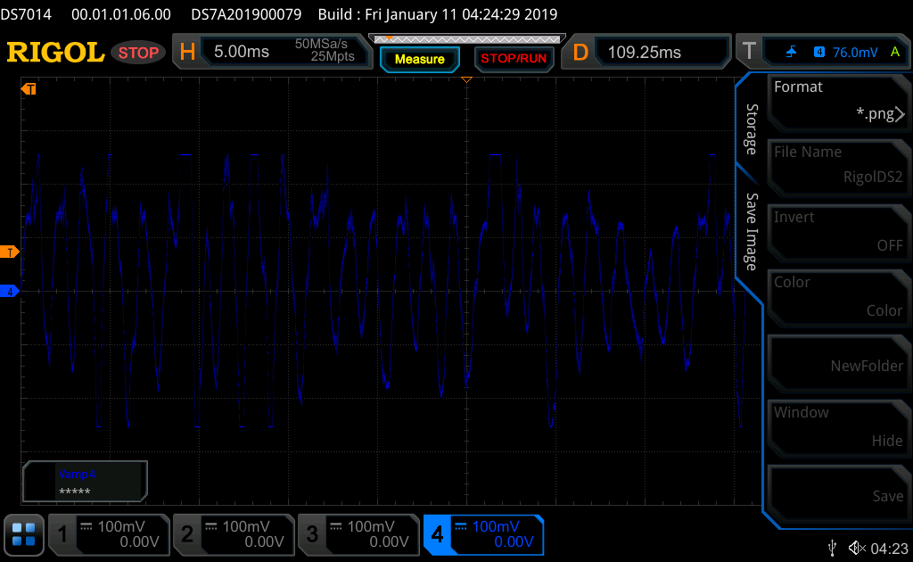
    But finally, when we ran the lab 3c, the motor didn't run well. Attached are the screenshots of what the current waveform looks like in a failed state (the current probe is set to 10mV/A).

    We'd like to screen share with you while the lab is running. You could see the oscope in real time and suggest things.

    On the other hand, you said that “the EVM kit can't support your motor to be run under full or heavy load limit to the maximum scale current of the EVM kit is not enough, just for identification or under a low light load.” Well, our strategy is to get our motor running on at the speed we need under the load we need, then copy the components and working software onto a custom board running the same processor. We estimate somewhere around 15-25A at 12V is our average power consumption. If it's not possible to achieve this using the eval board, what is going to need to change?

    Thanks for your help. Regards,

    Luciano

    user0110.h

  • Can you please provide the current waveforms for lab2c? I believe the motor parameters may not be correct, the current waveform looks bad. Are you running with light or no load here? The current appears to be saturating, as seen by the truncation of waveform at peak current.

    Can you try to run lab5a? lab3 does not provide much insight here as the offset is already known for a TI EVM

    If possible, please use a different color for the oscilloscope screenshot as blue is very hard for us to see against a black background

    Sean
  • Hi Luciano, have you had a chance to check into the previous questions I had?

    Sean
  • If there are no more updates from your end, I will close this thread for now

    Sean