


Part Number: LAUNCHXL-F280049C
Other Parts Discussed in Thread: C2000WARE
Tool/software: Code Composer Studio
Hi,
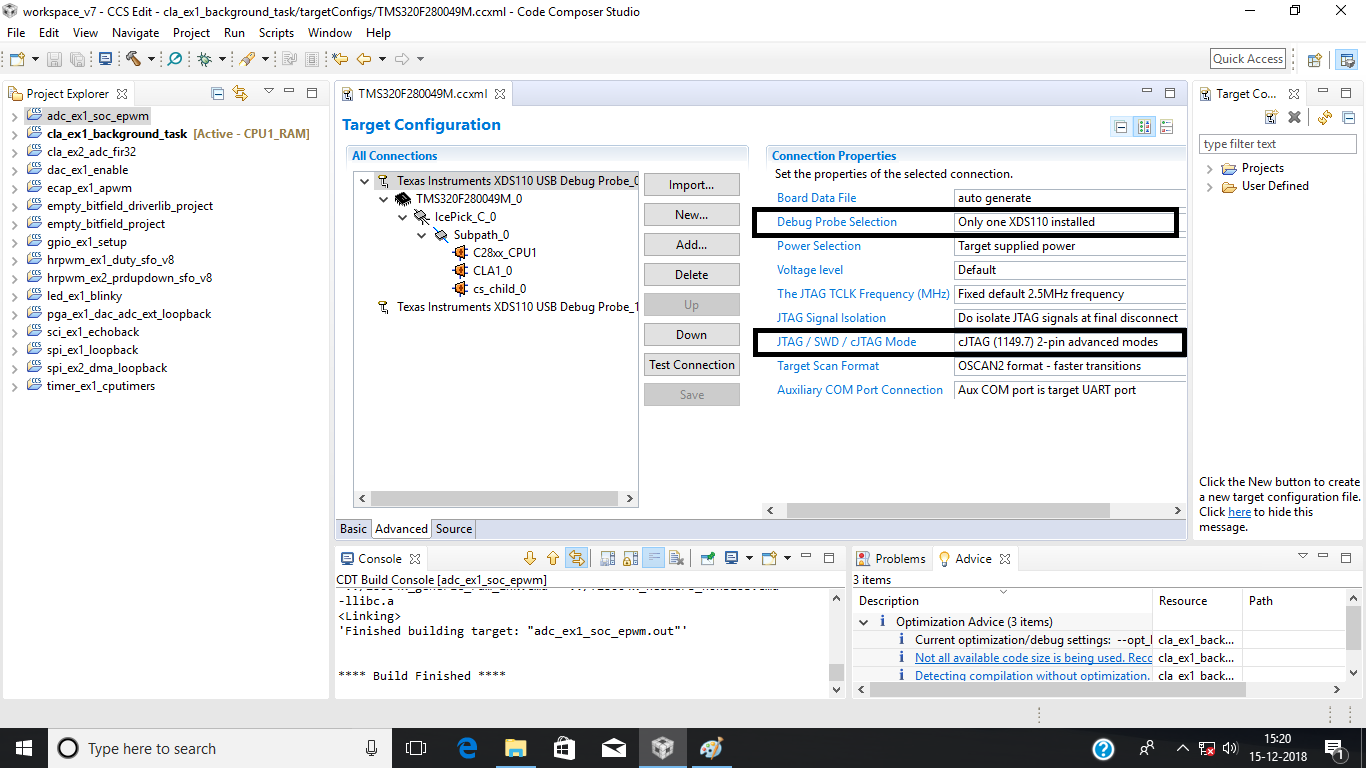
Recently i've bought Lauchxl-F280049C. As given in the quick start guide, i've downloaded & installed C2000Ware in the specified path (C:\\ti\C2000_xxx) and imported the examples given in the same folder for the respective device in CCS v7. As mentioned in the quick start guide page no.25 changed the target configuration file's JTAG/SWD/cJTAG Mode to cJTAG 2-Pin & tried connecting to the target. But it gives the following error
-----[An error has occurred and this utility has aborted]--------------------
This error is generated by TI's USCIF driver or utilities.
The value is '-233' (0xffffff17).
The title is 'SC_ERR_PATH_BROKEN'.
The explanation is:
The JTAG IR and DR scan-paths cannot circulate bits, they may be broken.
An attempt to scan the JTAG scan-path has failed.
The target's JTAG scan-path appears to be broken
with a stuck-at-ones or stuck-at-zero fault.
[End: Texas Instruments XDS110 USB Debug Probe_1]
I've attached the log files for your consideration.
I would appreciate if someone could help me out.
[Start: Texas Instruments XDS110 USB Debug Probe_0]

Execute the command:

%ccs_base%/common/uscif/dbgjtag -f %boarddatafile% -rv -o -S integrity

[Result]


-----[Print the board config pathname(s)]------------------------------------

C:\Users\Mokan\AppData\Local\TEXASI~1\CCS\
    ti\1\0\BrdDat\testBoard.dat

-----[Print the reset-command software log-file]-----------------------------

This utility has selected a 100- or 510-class product.
This utility will load the adapter 'jioxds110.dll'.
The library build date was 'Nov  6 2017'.
The library build time was '10:36:36'.
The library package version is '7.0.100.0'.
The library component version is '35.35.0.0'.
The controller does not use a programmable FPGA.
The controller has a version number of '5' (0x00000005).
The controller has an insertion length of '0' (0x00000000).
This utility will attempt to reset the controller.
This utility has successfully reset the controller.

-----[Print the reset-command hardware log-file]-----------------------------

The scan-path will be reset by toggling the JTAG TRST signal.
The controller is the XDS110 with USB interface.
The link from controller to target is direct (without cable).
The software is configured for XDS110 features.
The controller cannot monitor the value on the EMU[0] pin.
The controller cannot monitor the value on the EMU[1] pin.
The controller cannot control the timing on output pins.
The controller cannot control the timing on input pins.
The scan-path link-delay has been set to exactly '0' (0x0000).

-----[An error has occurred and this utility has aborted]--------------------

This error is generated by TI's USCIF driver or utilities.

The value is '-233' (0xffffff17).
The title is 'SC_ERR_PATH_BROKEN'.

The explanation is:
The JTAG IR and DR scan-paths cannot circulate bits, they may be broken.
An attempt to scan the JTAG scan-path has failed.
The target's JTAG scan-path appears to be broken
with a stuck-at-ones or stuck-at-zero fault.

[End: Texas Instruments XDS110 USB Debug Probe_0]

[Start: Texas Instruments XDS110 USB Debug Probe_1]

Execute the command:

%ccs_base%/common/uscif/dbgjtag -f %boarddatafile% -rv -o -S integrity

[Result]


-----[Print the board config pathname(s)]------------------------------------

C:\Users\Mokan\AppData\Local\TEXASI~1\CCS\
    ti\1\0\BrdDat\testBoard.dat

-----[Print the reset-command software log-file]-----------------------------

This utility has selected a 100- or 510-class product.
This utility will load the adapter 'jioxds110.dll'.
The library build date was 'Nov  6 2017'.
The library build time was '10:36:36'.
The library package version is '7.0.100.0'.
The library component version is '35.35.0.0'.
The controller does not use a programmable FPGA.
The controller has a version number of '5' (0x00000005).
The controller has an insertion length of '0' (0x00000000).
This utility will attempt to reset the controller.
This utility has successfully reset the controller.

-----[Print the reset-command hardware log-file]-----------------------------

The scan-path will be reset by toggling the JTAG TRST signal.
The controller is the XDS110 with USB interface.
The link from controller to target is direct (without cable).
The software is configured for XDS110 features.
The controller cannot monitor the value on the EMU[0] pin.
The controller cannot monitor the value on the EMU[1] pin.
The controller cannot control the timing on output pins.
The controller cannot control the timing on input pins.
The scan-path link-delay has been set to exactly '0' (0x0000).

-----[An error has occurred and this utility has aborted]--------------------

This error is generated by TI's USCIF driver or utilities.

The value is '-233' (0xffffff17).
The title is 'SC_ERR_PATH_BROKEN'.

The explanation is:
The JTAG IR and DR scan-paths cannot circulate bits, they may be broken.
An attempt to scan the JTAG scan-path has failed.
The target's JTAG scan-path appears to be broken
with a stuck-at-ones or stuck-at-zero fault.

[End: Texas Instruments XDS110 USB Debug Probe_1]


