This thread has been locked.

If you have a related question, please click the "Ask a related question" button in the top right corner. The newly created question will be automatically linked to this question.

CCS/LAUNCHXL2-570LC43: Hardware trace tool not working with XDS200

Part Number: LAUNCHXL2-570LC43
Other Parts Discussed in Thread: TMS570LC4357, TMDSEMUPROTRACE, , TMDX570LC43HDK

Tool/software: Code Composer Studio

Hello,

We are trying to use the hardware tracing capability of the XDS200 debug probe, following the Trace Analyzer User's Guide (Rev. B): http://www.ti.com/lit/ug/spruhm7b/spruhm7b.pdf

I believe that our chip (TMS570LC4357) should support hardware tracing, according to the technical reference manual (TRM) as well as the chip datasheet. However, after initializing the configurations for the different hardware trace analyzers, and upon launching the "Code Coverage" analyzer, I get the following error message:

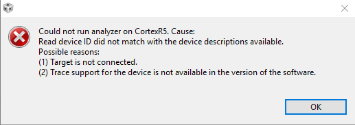
I'm confident that I have the XDS200 probe connected properly to our Launchpad, as I can successfully flash and step through the application code, and my version of CCS is 8.1.0.00011.

Thanks for any help,
James

  • James,

    The XDS200 is not a trace receiver. It supports SWO, which is a serial trace on Cortex M devices and it supports reading trace output from an embedded trace buffer (ETB).

    The TMS570 device you are using has ETM trace capabilities. It does not have an ETB so for this device the trace data is exported directly over pins. To support that you need a full trace receiver such as the TMDSEMUPROTRACE. That is a bit of an investment.

    Regards,
    John
  • John,

    Thanks for the reply. We've decided that we will try the Pro Trace, as you've suggested.

    After researching the probe, it seems like the target board requires a compatible JTAG header, which is a 60-pin MIPI HSPT or a TI 60-pin header. We currently have the LAUNCHXL2-570LC43 Launchpad. Correct me if I'm wrong, but I don't believe that our board has a compatible header. How would we go about connecting the XDS560v2 PRO TRACE to our Launchpad, or is it even possible?

    Thanks,
    James
  • James,

    I will get one of our experts to take a look at the LaunchPad. I know it has a spot for the 14pin JTAG header but for Trace you need more data pins.

    Regards,
    John
  • James Kiessling said:
    After researching the probe, it seems like the target board requires a compatible JTAG header, which is a 60-pin MIPI HSPT or a TI 60-pin header. We currently have the LAUNCHXL2-570LC43 Launchpad

    From a look at the LAUNCHXL2-570LC43 schematic the ETM signals are connected to J12 and J13 which are Hirose DF40C-60DP-0.4V(51) 0.40mm pitch connectors. To be able to connect to the XDS560v20 PRO TRACE to the LAUNCHXL2-570LC43 Launchpad you would need an adapter, and not sure if there are any off-the-shelf adapters.

    Whereas the TMDX570LC43HDK Hercules TMS570LC43x Development Kit uses the same TMS570LC4357 device as the launchpad, but the TMDX570LC43HDK has J19 which is a 60 Pin MIPI ETM Header which should allow direct connection of the XDS560v2 PRO TRACE.

  • Hi,

    Unfortunately we can't guarantee the ETM connections to J12 and J13 are suitable to perform ETM Trace, as they do not meet the stringent connection requirements validated by us and reported in the document below.

    www.ti.com/.../spru655i.pdf

    This interface depends on the processor but in my HDK board it calibrates at about 37MHz spread across 19 pins. Despite the speed is not terribly high, the major concern is the delay across all lines.

    Thus, as mentioned before, our recommendation is to get a TMDX570LC43HDK.

    Hope this helps,
    Rafael
  • Rafael,

    Thank you for the reply. We are in the process of creating a final product design that utilizes the TMS570LC43 processor, but we are moving away from the development boards (Launchpad and HDK). If we want to include support for the XDS560v2 PRO TRACE for tracing capability, are there any reference schematics or circuits available that we could use for our final design? Would the HDK schematic be sufficient for this purpose? Also, are there any other considerations we would need to make?

    Thank you,
    James
  • James,

    Yes, the HDK design (PCB + schematics) is suitable to add tracing capability on this device.

    Our golden reference is the document SPRU655 I mentioned before. Chapters 15 and 16 contain additional design information.

    There are several details to be followed, but one that used to be quite overlooked is to keep the tracks at the same length to avoid delays.

    If this device has multiplexed pins, you can try to use small resistors to switch between functions - something done on other boards we have in our portfolio. One example is the TMDSIDK574 and its schematics can be found at its page below:
    www.ti.com/.../tmdsidk574

    Hope this helps,
    Rafael