


Part Number: ADS1293
Other Parts Discussed in Thread: MSP430F5529,
Tool/software: Code Composer Studio
Hello,
I would like to ask about some things around ADS1293 and MSP430F5529. Now, I am acquiring data from ADS to MSP through SPI. I work in a Code Composer Studio and the first problem is how to display the data correctly in the graph in CCS. I do not know why, but there are different data (triangular shape) then I would like to display (ECG). In the case of the bigger amount of samples, I can display it correctly for example in Matlab.

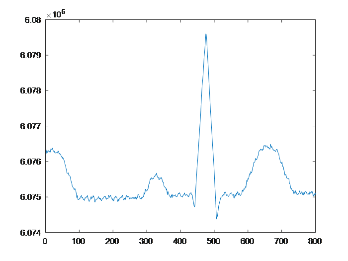
I would like to convert these ADC data (6074975 and so on) to the voltage as well. I found this equation in the datasheet of ADS1293 but I am not sure about the values Vinp and Vinm.

The last thing I would like to ask about is how to edit this code for a continuous reading a continuous plotting the graph. I am using demo3 from MSP430 Interface to ADS1293 Code Library. This is not the entire code, just the part with the acquiring of ECG data.
while (1)
  {
    if (ADS1293_ADCDataReady)
    {
      ADS1293_ADCDataReady = 0;                                                // clear flag
      TI_ADS1293_SPIStreamReadReg(read_buf, count);                            // read adc output into read_buf

      adc_data = ((uint32_t) read_buf[0] << 16)
                 | ((uint16_t) read_buf[1] << 8) | read_buf[2];                // form raw adc output data
      adc_sample_array[i] = adc_data;
      if (++i == SAMPLE_ARRAY_SIZE)                                            // sample array is full
      {
        process_adc_output(adc_sample_array);                                  // dummy app function: no error toggles led
        i = 0;
      }
    }
    __bis_SR_register(LPM0_bits + GIE);                                        // Enter LPM0, enable interrupts
    __no_operation();                                                          // For debugger
  }

void process_adc_output(uint32_t *data)
{
                                  // Toggle LED
}
//******************************************************************************
// TI_ADS1293_SPI_DRDYB_PIN interrupt service routine
#pragma vector=TI_ADS1293_DRDYB_VECTOR
__interrupt void TI_ADS1293_DRDY_PORTx(void)
{
  TI_ADS1293_DRDYB_PxIFG &= ~TI_ADS1293_DRDYB_PIN;                             //  IFG cleared
  ADS1293_ADCDataReady = 1;                                                    // set flag
  __bic_SR_register_on_exit(LPM0_bits);                                        // Exit active CPU
}
//******************************************************************************
//EOF
I will be glad for any advice regarding these problems.
Thank you for patience with me,
Daniel
