This thread has been locked.

If you have a related question, please click the "Ask a related question" button in the top right corner. The newly created question will be automatically linked to this question.

CCS/TM4C1294NCPDT: Not showing USB COM port in Device manager for usb_dev_bulk example

Part Number: TM4C1294NCPDT
Other Parts Discussed in Thread: EK-TM4C129EXL, EK-TM4C1294XL

Tool/software: Code Composer Studio

Hi,

I have dump the usb_dev_bulk example (C:\ti\TivaWare_C_Series-2.1.4.178\examples\boards\ek-tm4c129exl\usb_dev_bulk). After dumping the code I was removed the USB cable and changed the JP1 POWER

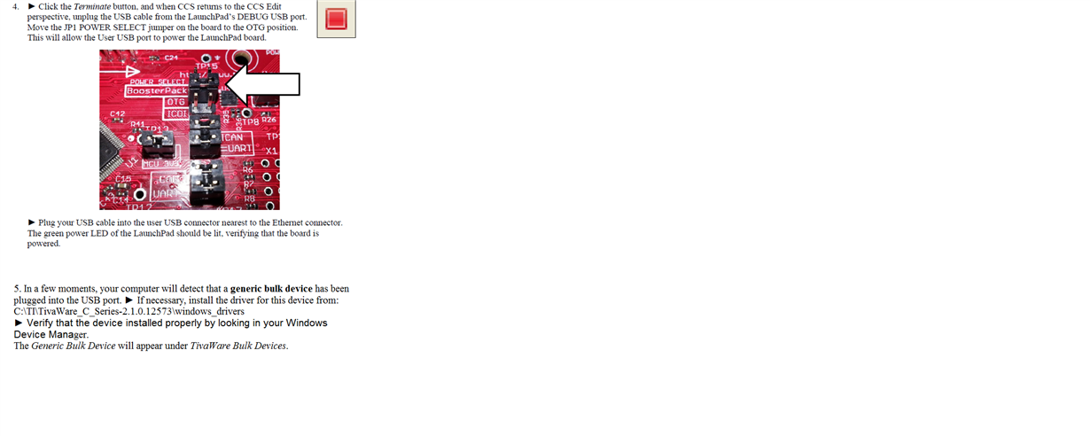
SELECT from ICDI to OTG position and connected the USB cable which is beside to the Ethernet port. In device manager it has to show the  Generic Bulk Device under TivaWare Bulk Devices  but it is not

detecting. I have already downloaded the windows_drivers (C:\TI\TivaWare_C_Series-2.1.4.178\windows_drivers) and I am using the EK-TM4C1294XL Launchpad.

Please suggest some solution so that I can further proceed.


Thanks & Regards,

Anamika

  • Hello Anamika,

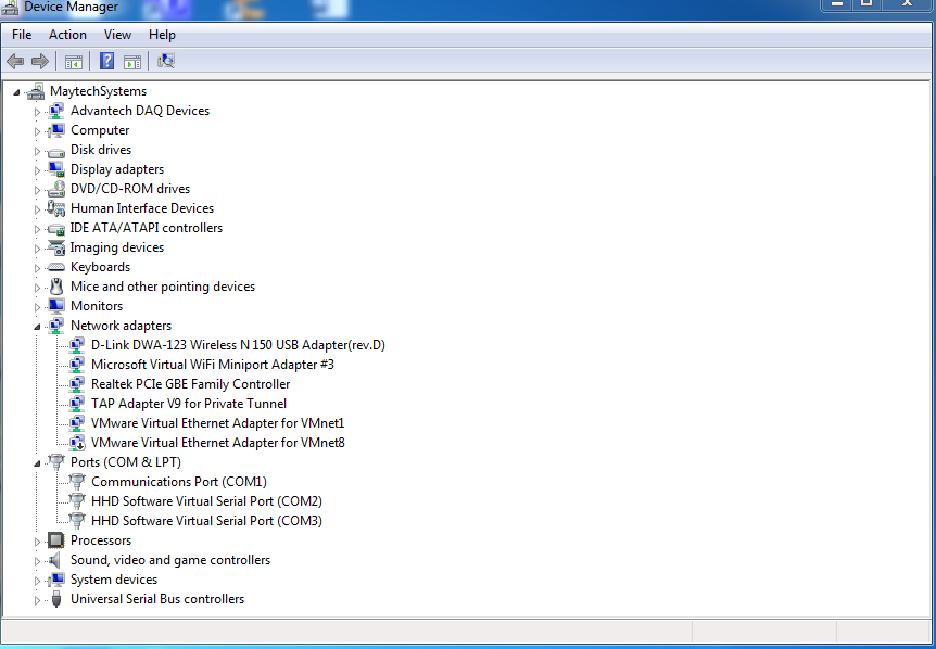
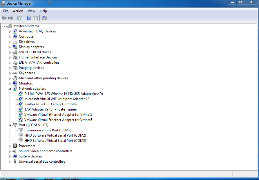
    Can you please post a screenshot of your device manager before and after the device is plugged in so I can see exactly how the device is enumerating in the system?

    Also which OS are you using, Windows 10?
  • Hi Ralph Jacobi,

    Thank you for your quick response.

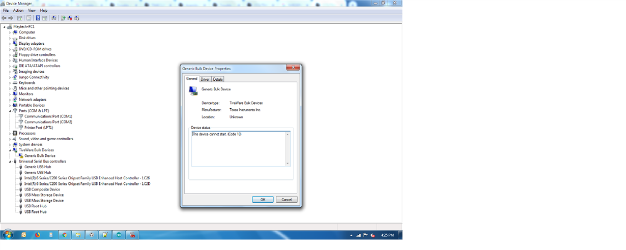
    When device is not plugged in...

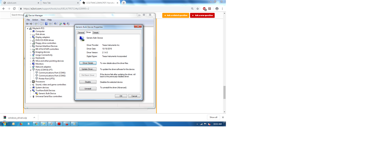
    and I changed the JP1 POWER SELECT from ICDI to the OTG position , and device is plugged in .... at that time my device manager is detecting nothing like below...

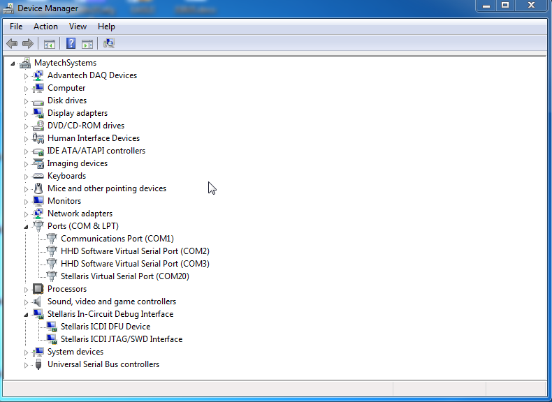
    When I was connected to the USB Debug port , it is detecting like below

    I am using Windows7....


    Thanks & Regards

    Anamika

  • Hello Anamika,

    Thank you for the comprehensive screenshots.

    Some items to check to try and resolve this issue:

    1) Are you programming the device with CCS? If not, can you do a Verify for the program?

    2) When plugging in only the cable by the Ethernet port and switching the jumper to OTG, does the power LED come on for the LaunchPad?

    3) With both cables plugged in and the power jumper set to ICDI, do you see anything different?

    4) With both cables plugged in, can you look inside of 'Universal Serial Bus controllers' and see if there are any devices showing up as not installed properly?

    5) Can you try using a new USB cable for the Bulk device port? Occasionally a faulty cable can be the root cause.
  • Hi Ralph Jacobi,


     1) Are you programming the device with CCS? If not, can you do a Verify for the program?

         Yes, I am doing the programming to the device with CCS.

    2) When plugging in only the cable by the Ethernet port and switching the jumper to OTG, does the power LED come on for the Launchpad?

        After plugging the cable by the Ethernet port and switching the to OTG, Power LED does not come on for the Launchpad.

    3) With both cables plugged in and the power jumper set to ICDI, do you see anything different?

       After both cables plugged in and the jumper set to ICDI , only stellaris debug port is detecting. kindly go through the below screenshot.

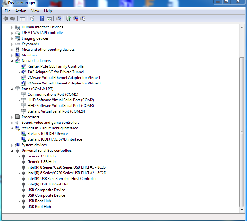
    4) With both cables plugged in, can you look inside of 'Universal Serial Bus controllers' and see if there are any devices showing up as not installed properly?


    5) Can you try using a new USB cable for the Bulk device port? Occasionally a faulty cable can be the root cause.

    Yes , I was tried with new USB cable for the Bulk device port but nothing is detecting in device manager.

    And also I have tried with new Launchpad , there also Bulk device port is not detecting.

  • Hello Anamika,

    Anamika Kumari said:

    2) When plugging in only the cable by the Ethernet port and switching the jumper to OTG, does the power LED come on for the Launchpad?

        After plugging the cable by the Ethernet port and switching the to OTG, Power LED does not come on for the Launchpad.

    That doesn't seem like the right behavior, so I wonder if the USB bulk program did not flash properly or if that port on the LaunchPad is not working right.

    Have you tried any other USB examples? Can you try using the usb_dev_cserial example and see if anything changes?

    Actually, on that note... I presume those 2 USB Composite Devices are always there and do not disappear when you unplug the board? I ask because usb_dev_cserial would appear like that, so maybe you have the wrong project loaded somehow?

  • Hii Ralph

    2) When plugging in only the cable by the Ethernet port and switching the jumper to OTG, does the power LED come on for the LaunchPad?

    As you told to check, but no power is coming in Launchpad

    Can you please tell me the relation between the Ethernet port with Power in Launchpad by changing the Power Jumper from ICDI position to OTG position . How you are linking this with the USB.

    I have checked with Some blinking Led code . After dumping the code I have disconnected ICDI position and connected the USB nearest to the Ethernet port and move the Power Jumper to OTG position and this working fine, means processor is working after connecting to the USB.


    Thanks & Regard
    Anamika
  • Hello Anamika,

    I was not talking about the Ethernet port itself, but the USB plug next to it. I used that terminology as that was how you described that port in your first post: "SELECT from ICDI to OTG position and connected the USB cable which is beside to the Ethernet port. "
  • Hii Ralph

    Sorry for misconception.

    "SELECT from ICDI to OTG position and connected the USB cable which is beside to the Ethernet port. "

    I followed the same procedure as you mentioned above, Power led is coming on the board but USB port is not detecting and also its not showing to install the related drivers or update the drivers.

    Kindly go through the below screenshot which I followed:

    As I have checked with Some blinking Led code . After dumping the code,I have disconnected ICDI position and connected  USB beside to the Ethernet port and move the Power Jumper to OTG position . Power led is  coming on the Launchpad and code also running, means processor is working after connecting to the USB beside to Ethernet.

  • Hello Anamika,

    Okay it sounds like the board is getting power correctly and can execute code when the jumper is set right. Have you then tried uploading any USB examples since then?

    I recommend starting with usb_dev_cserial as that is typically easiest to see how the USB ports are enumerating.

    If that works, then try usb_dev_bulk next.
  • Hi Ralph Jacobi,

    Sir I had tried with usb_dev_cserial example code but still USB-COM Port is not detecting. I have tried with different Launchpad , different cables and related drivers but still I am facing same problem. If you want to recommend USB related example code or drivers and procedure...kindly give me the link for that.....

    Thanks & Regards,

    Anamika

  • Hii Ralph

    I have use the below examples code for USB_DEV_SERIAL And USB_DEV_BULK and kindly suggest if is there any changes to add.

    Kindly go through the below attached files.

    usb_dev_bulk.c
    //*****************************************************************************
    //
    // usb_dev_bulk.c - Main routines for the generic bulk device example.
    //
    // Copyright (c) 2013-2017 Texas Instruments Incorporated.  All rights reserved.
    // Software License Agreement
    // 
    // Texas Instruments (TI) is supplying this software for use solely and
    // exclusively on TI's microcontroller products. The software is owned by
    // TI and/or its suppliers, and is protected under applicable copyright
    // laws. You may not combine this software with "viral" open-source
    // software in order to form a larger program.
    // 
    // THIS SOFTWARE IS PROVIDED "AS IS" AND WITH ALL FAULTS.
    // NO WARRANTIES, WHETHER EXPRESS, IMPLIED OR STATUTORY, INCLUDING, BUT
    // NOT LIMITED TO, IMPLIED WARRANTIES OF MERCHANTABILITY AND FITNESS FOR
    // A PARTICULAR PURPOSE APPLY TO THIS SOFTWARE. TI SHALL NOT, UNDER ANY
    // CIRCUMSTANCES, BE LIABLE FOR SPECIAL, INCIDENTAL, OR CONSEQUENTIAL
    // DAMAGES, FOR ANY REASON WHATSOEVER.
    // 
    // This is part of revision 2.1.4.178 of the EK-TM4C1294XL Firmware Package.
    //
    //*****************************************************************************
    
    #include <stdbool.h>
    #include <stdint.h>
    #include "inc/hw_ints.h"
    #include "driverlib/interrupt.h"
    #include "driverlib/sysctl.h"
    #include "driverlib/systick.h"
    #include "driverlib/rom.h"
    #include "driverlib/rom_map.h"
    #include "usblib/usblib.h"
    #include "usblib/usb-ids.h"
    #include "usblib/device/usbdevice.h"
    #include "usblib/device/usbdbulk.h"
    #include "utils/uartstdio.h"
    #include "utils/ustdlib.h"
    #include "drivers/pinout.h"
    #include "usb_bulk_structs.h"
    
    //*****************************************************************************
    //
    //! \addtogroup example_list
    //! <h1>USB Generic Bulk Device (usb_dev_bulk)</h1>
    //!
    //! This example provides a generic USB device offering simple bulk data
    //! transfer to and from the host.  The device uses a vendor-specific class ID
    //! and supports a single bulk IN endpoint and a single bulk OUT endpoint.
    //! Data received from the host is assumed to be ASCII text and it is
    //! echoed back with the case of all alphabetic characters swapped.
    //!
    //! A Windows INF file for the device is provided on the installation media and
    //! in the C:/ti/TivaWare-C-Series-X.X/windows_drivers directory of TivaWare
    //! releases.  This INF contains information required to install the WinUSB
    //! subsystem on WindowsXP and Vista PCs.  WinUSB is a Windows subsystem
    //! allowing user mode applications to access the USB device without the need
    //! for a vendor-specific kernel mode driver.
    //!
    //! A sample Windows command-line application, usb_bulk_example, illustrating
    //! how to connect to and communicate with the bulk device is also provided.
    //! The application binary is installed as part of the ``TivaWare for C Series
    //! PC Companion Utilities'' package (SW-TM4C-USB-WIN) on the installation CD
    //! or via download from http://www.ti.com/tivaware .  Project files are
    //! included to allow the examples to be built using
    //! Microsoft Visual Studio 2008.  Source code for this application can be
    //! found in directory ti/TivaWare_C_Series-x.x/tools/usb_bulk_example.
    //
    //*****************************************************************************
    
    
    //*****************************************************************************
    //
    // The system tick rate expressed both as ticks per second and a millisecond
    // period.
    //
    //*****************************************************************************
    #define SYSTICKS_PER_SECOND 100
    #define SYSTICK_PERIOD_MS   (1000 / SYSTICKS_PER_SECOND)
    
    //*****************************************************************************
    //
    // The global system tick counter.
    //
    //*****************************************************************************
    volatile uint32_t g_ui32SysTickCount = 0;
    
    //*****************************************************************************
    //
    // Variables tracking transmit and receive counts.
    //
    //*****************************************************************************
    volatile uint32_t g_ui32TxCount = 0;
    volatile uint32_t g_ui32RxCount = 0;
    
    //*****************************************************************************
    //
    // Flags used to pass commands from interrupt context to the main loop.
    //
    //*****************************************************************************
    #define COMMAND_PACKET_RECEIVED 0x00000001
    #define COMMAND_STATUS_UPDATE   0x00000002
    
    volatile uint32_t g_ui32Flags = 0;
    
    //*****************************************************************************
    //
    // Global flag indicating that a USB configuration has been set.
    //
    //*****************************************************************************
    static volatile bool g_bUSBConfigured = false;
    
    //*****************************************************************************
    //
    // The error routine that is called if the driver library encounters an error.
    //
    //*****************************************************************************
    #ifdef DEBUG
    void
    __error__(char *pcFilename, uint32_t ui32Line)
    {
    }
    #endif
    
    //*****************************************************************************
    //
    // Interrupt handler for the system tick counter.
    //
    //*****************************************************************************
    void
    SysTickIntHandler(void)
    {
        //
        // Update our system tick counter.
        //
        g_ui32SysTickCount++;
    }
    
    //*****************************************************************************
    //
    // Receive new data and echo it back to the host.
    //
    // \param psDevice points to the instance data for the device whose data is to
    // be processed.
    // \param pi8Data points to the newly received data in the USB receive buffer.
    // \param ui32NumBytes is the number of bytes of data available to be
    // processed.
    //
    // This function is called whenever we receive a notification that data is
    // available from the host. We read the data, byte-by-byte and swap the case
    // of any alphabetical characters found then write it back out to be
    // transmitted back to the host.
    //
    // \return Returns the number of bytes of data processed.
    //
    //*****************************************************************************
    static uint32_t
    EchoNewDataToHost(tUSBDBulkDevice *psDevice, uint8_t *pi8Data,
                      uint_fast32_t ui32NumBytes)
    {
        uint_fast32_t ui32Loop, ui32Space, ui32Count;
        uint_fast32_t ui32ReadIndex;
        uint_fast32_t ui32WriteIndex;
        tUSBRingBufObject sTxRing;
    
        //
        // Get the current buffer information to allow us to write directly to
        // the transmit buffer (we already have enough information from the
        // parameters to access the receive buffer directly).
        //
        USBBufferInfoGet(&g_sTxBuffer, &sTxRing);
    
        //
        // How much space is there in the transmit buffer?
        //
        ui32Space = USBBufferSpaceAvailable(&g_sTxBuffer);
    
        //
        // How many characters can we process this time round?
        //
        ui32Loop = (ui32Space < ui32NumBytes) ? ui32Space : ui32NumBytes;
        ui32Count = ui32Loop;
    
        //
        // Update our receive counter.
        //
        g_ui32RxCount += ui32NumBytes;
    
        //
        // Set up to process the characters by directly accessing the USB buffers.
        //
        ui32ReadIndex = (uint32_t)(pi8Data - g_pui8USBRxBuffer);
        ui32WriteIndex = sTxRing.ui32WriteIndex;
    
        while(ui32Loop)
        {
            //
            // Copy from the receive buffer to the transmit buffer converting
            // character case on the way.
            //
    
            //
            // Is this a lower case character?
            //
            if((g_pui8USBRxBuffer[ui32ReadIndex] >= 'a') &&
               (g_pui8USBRxBuffer[ui32ReadIndex] <= 'z'))
            {
                //
                // Convert to upper case and write to the transmit buffer.
                //
                g_pui8USBTxBuffer[ui32WriteIndex] =
                    (g_pui8USBRxBuffer[ui32ReadIndex] - 'a') + 'A';
            }
            else
            {
                //
                // Is this an upper case character?
                //
                if((g_pui8USBRxBuffer[ui32ReadIndex] >= 'A') &&
                   (g_pui8USBRxBuffer[ui32ReadIndex] <= 'Z'))
                {
                    //
                    // Convert to lower case and write to the transmit buffer.
                    //
                    g_pui8USBTxBuffer[ui32WriteIndex] =
                        (g_pui8USBRxBuffer[ui32ReadIndex] - 'Z') + 'z';
                }
                else
                {
                    //
                    // Copy the received character to the transmit buffer.
                    //
                    g_pui8USBTxBuffer[ui32WriteIndex] =
                        g_pui8USBRxBuffer[ui32ReadIndex];
                }
            }
    
            //
            // Move to the next character taking care to adjust the pointer for
            // the buffer wrap if necessary.
            //
            ui32WriteIndex++;
            ui32WriteIndex =
                (ui32WriteIndex == BULK_BUFFER_SIZE) ? 0 : ui32WriteIndex;
    
            ui32ReadIndex++;
    
            ui32ReadIndex = ((ui32ReadIndex == BULK_BUFFER_SIZE) ?
                             0 : ui32ReadIndex);
    
            ui32Loop--;
        }
    
        //
        // We've processed the data in place so now send the processed data
        // back to the host.
        //
        USBBufferDataWritten(&g_sTxBuffer, ui32Count);
    
        //
        // We processed as much data as we can directly from the receive buffer so
        // we need to return the number of bytes to allow the lower layer to
        // update its read pointer appropriately.
        //
        return(ui32Count);
    }
    
    //*****************************************************************************
    //
    // Handles bulk driver notifications related to the transmit channel (data to
    // the USB host).
    //
    // \param pvCBData is the client-supplied callback pointer for this channel.
    // \param ulEvent identifies the event we are being notified about.
    // \param ulMsgValue is an event-specific value.
    // \param pvMsgData is an event-specific pointer.
    //
    // This function is called by the bulk driver to notify us of any events
    // related to operation of the transmit data channel (the IN channel carrying
    // data to the USB host).
    //
    // \return The return value is event-specific.
    //
    //*****************************************************************************
    uint32_t
    TxHandler(void *pvCBData, uint32_t ui32Event, uint32_t ui32MsgValue,
              void *pvMsgData)
    {
        //
        // We are not required to do anything in response to any transmit event
        // in this example. All we do is update our transmit counter.
        //
        if(ui32Event == USB_EVENT_TX_COMPLETE)
        {
            g_ui32TxCount += ui32MsgValue;
        }
        return(0);
    }
    
    //*****************************************************************************
    //
    // Handles bulk driver notifications related to the receive channel (data from
    // the USB host).
    //
    // \param pvCBData is the client-supplied callback pointer for this channel.
    // \param ui32Event identifies the event we are being notified about.
    // \param ui32MsgValue is an event-specific value.
    // \param pvMsgData is an event-specific pointer.
    //
    // This function is called by the bulk driver to notify us of any events
    // related to operation of the receive data channel (the OUT channel carrying
    // data from the USB host).
    //
    // \return The return value is event-specific.
    //
    //*****************************************************************************
    uint32_t
    RxHandler(void *pvCBData, uint32_t ui32Event, uint32_t ui32MsgValue,
              void *pvMsgData)
    {
        //
        // Which event are we being sent?
        //
        switch(ui32Event)
        {
            //
            // We are connected to a host and communication is now possible.
            //
            case USB_EVENT_CONNECTED:
            {
                g_bUSBConfigured = true;
                g_ui32Flags |= COMMAND_STATUS_UPDATE;
    
                //
                // Flush our buffers.
                //
                USBBufferFlush(&g_sTxBuffer);
                USBBufferFlush(&g_sRxBuffer);
    
                break;
            }
    
            //
            // The host has disconnected.
            //
            case USB_EVENT_DISCONNECTED:
            {
                g_bUSBConfigured = false;
                g_ui32Flags |= COMMAND_STATUS_UPDATE;
                break;
            }
    
            //
            // A new packet has been received.
            //
            case USB_EVENT_RX_AVAILABLE:
            {
                tUSBDBulkDevice *psDevice;
    
                //
                // Get a pointer to our instance data from the callback data
                // parameter.
                //
                psDevice = (tUSBDBulkDevice *)pvCBData;
    
                //
                // Read the new packet and echo it back to the host.
                //
                return(EchoNewDataToHost(psDevice, pvMsgData, ui32MsgValue));
            }
    
            //
            // Ignore SUSPEND and RESUME for now.
            //
            case USB_EVENT_SUSPEND:
            case USB_EVENT_RESUME:
                break;
    
            //
            // Ignore all other events and return 0.
            //
            default:
                break;
        }
    
        return(0);
    }
    
    //*****************************************************************************
    //
    // This is the main application entry function.
    //
    //*****************************************************************************
    int
    main(void)
    {
        uint_fast32_t ui32TxCount;
        uint_fast32_t ui32RxCount;
        uint32_t ui32SysClock;
        uint32_t ui32PLLRate;
    
        //
        // Run from the PLL at 120 MHz.
        //
        ui32SysClock = MAP_SysCtlClockFreqSet((SYSCTL_XTAL_25MHZ |
                                               SYSCTL_OSC_MAIN |
                                               SYSCTL_USE_PLL |
                                               SYSCTL_CFG_VCO_480), 120000000);
    
        //
        // Configure the device pins.
        //
        PinoutSet(false, true);
    
        //
        // Enable UART0
        //
        ROM_SysCtlPeripheralEnable(SYSCTL_PERIPH_UART0);
    
        //
        // Initialize the UART for console I/O.
        //
        UARTStdioConfig(0, 115200, ui32SysClock);
    
        //
        // Not configured initially.
        //
        g_bUSBConfigured = false;
    
        //
        // Enable the system tick.
        //
        ROM_SysTickPeriodSet(ui32SysClock / SYSTICKS_PER_SECOND);
        ROM_SysTickIntEnable();
        ROM_SysTickEnable();
    
        //
        // Show the application name on the display and UART output.
        //
        UARTprintf("\033[2J\nTiva C Series USB bulk device example\n");
        UARTprintf("---------------------------------\n\n");
    
        //
        // Tell the user what we are up to.
        //
        UARTprintf("Configuring USB... \n");
    
        //
        // Initialize the transmit and receive buffers.
        //
        USBBufferInit(&g_sTxBuffer);
        USBBufferInit(&g_sRxBuffer);
    
        //
        // Tell the USB library the CPU clock and the PLL frequency.  This is a
        // new requirement for TM4C129 devices.
        //
        SysCtlVCOGet(SYSCTL_XTAL_25MHZ, &ui32PLLRate);
        USBDCDFeatureSet(0, USBLIB_FEATURE_CPUCLK, &ui32SysClock);
        USBDCDFeatureSet(0, USBLIB_FEATURE_USBPLL, &ui32PLLRate);
    
        //
        // Initialize the USB stack for device mode.
        //
        USBStackModeSet(0, eUSBModeDevice, 0);
    
        //
        // Pass our device information to the USB library and place the device
        // on the bus.
        //
        USBDBulkInit(0, &g_sBulkDevice);
    
        //
        // Wait for initial configuration to complete.
        //
        UARTprintf("Waiting for host...\r");
    
        //
        // Clear our local byte counters.
        //
        ui32RxCount = 0;
        ui32TxCount = 0;
    
        //
        // Main application loop.
        //
        while(1)
        {
            //
            // Have we been asked to update the status display?
            //
            if(g_ui32Flags & COMMAND_STATUS_UPDATE)
            {
                g_ui32Flags &= ~COMMAND_STATUS_UPDATE;
    
                if(g_bUSBConfigured)
                {
                    UARTprintf("Host Connected.            \n\n");
                    UARTprintf("Data transferred:\n");
                    UARTprintf("TX: %d  RX: %d                    \r",
                               g_ui32TxCount,
                               g_ui32RxCount);
                }
                else
                {
                    UARTprintf("\n\nHost Disconnected.\n\n");
                }
            }
    
            //
            // Has there been any transmit traffic since we last checked?
            //
            if(ui32TxCount != g_ui32TxCount)
            {
                //
                // Take a snapshot of the latest transmit count.
                //
                ui32TxCount = g_ui32TxCount;
    
                //
                // Update the displayed buffer count information.
                //
                UARTprintf("TX: %d  RX: %d                    \r",
                           g_ui32TxCount,
                           g_ui32RxCount);
            }
    
            //
            // Has there been any receive traffic since we last checked?
            //
            if(ui32RxCount != g_ui32RxCount)
            {
                //
                // Take a snapshot of the latest receive count.
                //
                ui32RxCount = g_ui32RxCount;
    
                //
                // Update the displayed buffer count information.
                //
                UARTprintf("TX: %d  RX: %d                    \r",
                           g_ui32TxCount,
                           g_ui32RxCount);
            }
        }
    }
    

    usb_dev_cserial.c
    //****************************************************************************
    //
    // usb_dev_cserial.c - Main routines for the USB CDC composite serial example.
    //
    // Copyright (c) 2010-2017 Texas Instruments Incorporated.  All rights reserved.
    // Software License Agreement
    // 
    // Texas Instruments (TI) is supplying this software for use solely and
    // exclusively on TI's microcontroller products. The software is owned by
    // TI and/or its suppliers, and is protected under applicable copyright
    // laws. You may not combine this software with "viral" open-source
    // software in order to form a larger program.
    // 
    // THIS SOFTWARE IS PROVIDED "AS IS" AND WITH ALL FAULTS.
    // NO WARRANTIES, WHETHER EXPRESS, IMPLIED OR STATUTORY, INCLUDING, BUT
    // NOT LIMITED TO, IMPLIED WARRANTIES OF MERCHANTABILITY AND FITNESS FOR
    // A PARTICULAR PURPOSE APPLY TO THIS SOFTWARE. TI SHALL NOT, UNDER ANY
    // CIRCUMSTANCES, BE LIABLE FOR SPECIAL, INCIDENTAL, OR CONSEQUENTIAL
    // DAMAGES, FOR ANY REASON WHATSOEVER.
    // 
    // This is part of revision 2.1.4.178 of the EK-TM4C1294XL Firmware Package.
    //
    //****************************************************************************
    
    #include <stdbool.h>
    #include <stdint.h>
    #include "inc/hw_ints.h"
    #include "inc/hw_memmap.h"
    #include "inc/hw_types.h"
    #include "inc/hw_uart.h"
    #include "driverlib/debug.h"
    #include "driverlib/gpio.h"
    #include "driverlib/interrupt.h"
    #include "driverlib/rom.h"
    #include "driverlib/rom_map.h"
    #include "driverlib/sysctl.h"
    #include "driverlib/systick.h"
    #include "driverlib/timer.h"
    #include "driverlib/uart.h"
    #include "driverlib/usb.h"
    #include "usblib/usblib.h"
    #include "usblib/usbcdc.h"
    #include "usblib/usb-ids.h"
    #include "usblib/device/usbdevice.h"
    #include "usblib/device/usbdcomp.h"
    #include "usblib/device/usbdcdc.h"
    #include "utils/cmdline.h"
    #include "utils/ustdlib.h"
    #include "drivers/pinout.h"
    #include "usb_structs.h"
    
    //****************************************************************************
    //
    //! \addtogroup example_list
    //! <h1>USB Composite Serial Device (usb_dev_cserial)</h1>
    //!
    //! This example application turns the evaluation kit into a multiple virtual
    //! serial ports when connected to the USB host system.  The application
    //! supports the USB Communication Device Class, Abstract Control Model to
    //! redirect UART0 traffic to and from the USB host system.  For this example,
    //! the evaluation kit will enumerate as a composite device with two virtual
    //! serial ports. Including the physical UART0 connection with the ICDI, this
    //! means that three independent virtual serial ports will be visible to the
    //! USB host.
    //!
    //! The first virtual serial port will echo data to the physical UART0 port on
    //! the device which is connected to the virtual serial port on the ICDI device
    //! on this board. The physical UART0 will also echo onto the first virtual
    //! serial device provided by the Stellaris controller.
    //!
    //! The second Stellaris virtual serial port will provide a console that can
    //! echo data to both the ICDI virtual serial port and the first Stellaris
    //! virtual serial port.  It will also allow turning on, off or toggling the
    //! boards led status.  Typing a "?" and pressing return should echo a list of
    //! commands to the terminal, since this board can show up as possibly three
    //! individual virtual serial devices.
    //!
    //! Assuming you installed TivaWare in the default directory, a driver
    //! information (INF) file for use with Windows XP, Windows Vista and Windows7
    //! can be found in C:/TivaWare_C_Series-x.x/windows_drivers. For Windows 2000,
    //! the required INF file is in C:/TivaWare_C_Series-x.x/windows_drivers/win2K.
    //
    //*****************************************************************************
    
    //****************************************************************************
    //
    // Note:
    //
    // This example is intended to run on Stellaris evaluation kit hardware
    // where the UARTs are wired solely for TX and RX, and do not have GPIOs
    // connected to act as handshake signals.  As a result, this example mimics
    // the case where communication is always possible.  It reports DSR, DCD
    // and CTS as high to ensure that the USB host recognizes that data can be
    // sent and merely ignores the host's requested DTR and RTS states.  "TODO"
    // comments in the code indicate where code would be required to add support
    // for real handshakes.
    //
    //****************************************************************************
    
    
    //****************************************************************************
    //
    // The system tick rate expressed both as ticks per second and a millisecond
    // period.
    //
    //****************************************************************************
    #define SYSTICKS_PER_SECOND 100
    #define SYSTICK_PERIOD_MS (1000 / SYSTICKS_PER_SECOND)
    
    //*****************************************************************************
    //
    // Variable to remember our clock frequency
    //
    //*****************************************************************************
    uint32_t g_ui32SysClock = 0;
    
    //****************************************************************************
    //
    // Variables tracking transmit and receive counts.
    //
    //****************************************************************************
    volatile uint32_t g_ui32UARTTxCount = 0;
    volatile uint32_t g_ui32UARTRxCount = 0;
    
    //****************************************************************************
    //
    // Default line coding settings for the redirected UART.
    //
    //****************************************************************************
    #define DEFAULT_BIT_RATE        115200
    #define DEFAULT_UART_CONFIG     (UART_CONFIG_WLEN_8 | UART_CONFIG_PAR_NONE | \
                                     UART_CONFIG_STOP_ONE)
    
    //****************************************************************************
    //
    // GPIO peripherals and pins muxed with the redirected UART.  These will
    // depend upon the IC in use and the UART selected in UART0_BASE.  Be careful
    // that these settings all agree with the hardware you are using.
    //
    //****************************************************************************
    #define TX_GPIO_BASE            GPIO_PORTA_BASE
    #define TX_GPIO_PERIPH          SYSCTL_PERIPH_GPIOA
    #define TX_GPIO_PIN             GPIO_PIN_1
    
    #define RX_GPIO_BASE            GPIO_PORTA_BASE
    #define RX_GPIO_PERIPH          SYSCTL_PERIPH_GPIOA
    #define RX_GPIO_PIN             GPIO_PIN_0
    
    //****************************************************************************
    //
    // The LED control macros.
    //
    //****************************************************************************
    #define LEDOn()  ROM_GPIOPinWrite(CLP_D1_PORT, CLP_D1_PIN, CLP_D1_PIN);
    
    #define LEDOff() ROM_GPIOPinWrite(CLP_D1_PORT, CLP_D1_PIN, 0)
    #define LEDToggle()                                                         \
            ROM_GPIOPinWrite(CLP_D1_PORT, CLP_D1_PIN,                           \
                             (ROM_GPIOPinRead(CLP_D1_PORT, CLP_D1_PIN) ^        \
                              CLP_D1_PIN));
    
    //****************************************************************************
    //
    // Character sequence sent to the serial terminal to implement a character
    // erase when backspace is pressed.
    //
    //****************************************************************************
    static const char g_pcBackspace[3] = {0x08, ' ', 0x08};
    
    //****************************************************************************
    //
    // Defines the size of the buffer that holds the command line.
    //
    //****************************************************************************
    #define CMD_BUF_SIZE            256
    
    //****************************************************************************
    //
    // The buffer that holds the command line.
    //
    //****************************************************************************
    static char g_pcCmdBuf[CMD_BUF_SIZE];
    static uint32_t ui32CmdIdx;
    
    //****************************************************************************
    //
    // Flag indicating whether or not we are currently sending a Break condition.
    //
    //****************************************************************************
    static bool g_bSendingBreak = false;
    
    //****************************************************************************
    //
    // Global system tick counter
    //
    //****************************************************************************
    volatile uint32_t g_ui32SysTickCount = 0;
    
    //****************************************************************************
    //
    // The memory allocated to hold the composite descriptor that is created by
    // the call to USBDCompositeInit().
    //
    //****************************************************************************
    uint8_t g_pucDescriptorData[DESCRIPTOR_DATA_SIZE];
    
    //****************************************************************************
    //
    // Flags used to pass commands from interrupt context to the main loop.
    //
    //****************************************************************************
    #define COMMAND_PACKET_RECEIVED 0x00000001
    #define COMMAND_STATUS_UPDATE   0x00000002
    #define COMMAND_RECEIVED        0x00000004
    
    volatile uint32_t g_ui32Flags = 0;
    char *g_pcStatus;
    
    //****************************************************************************
    //
    // Global flag indicating that a USB configuration has been set.
    //
    //****************************************************************************
    static volatile bool g_bUSBConfigured = false;
    
    //****************************************************************************
    //
    // The error routine that is called if the driver library encounters an error.
    //
    //****************************************************************************
    #ifdef DEBUG
    void
    __error__(char *pcFilename, uint32_t ui32Line)
    {
        while(1)
        {
        }
    }
    #endif
    
    //****************************************************************************
    //
    // This function will print out to the console UART and not the echo UART.
    //
    //****************************************************************************
    void
    CommandPrint(const char *pcStr)
    {
        uint32_t ui32Index;
        const char cCR = 0xd;
    
        ui32Index = 0;
    
        while(pcStr[ui32Index] != 0)
        {
            //
            // Wait for space for two bytes in case there is a need to send out
            // the line feed plus the carriage return.
            //
            while(USBBufferSpaceAvailable(&g_psTxBuffer[1]) < 2)
            {
            }
    
            //
            // Print the next character.
            //
            USBBufferWrite(&g_psTxBuffer[1], (const uint8_t *)&pcStr[ui32Index],
                           1);
    
            //
            // If this is a line feed then send a carriage return as well.
            //
            if(pcStr[ui32Index] == 0xa)
            {
                USBBufferWrite(&g_psTxBuffer[1], (const uint8_t *)&cCR, 1);
            }
    
            ui32Index++;
        }
    }
    
    //****************************************************************************
    //
    // This function is called whenever serial data is received from the UART.
    // It is passed the accumulated error flags from each character received in
    // this interrupt and determines from them whether or not an interrupt
    // notification to the host is required.
    //
    // If a notification is required and the control interrupt endpoint is idle,
    // we send the notification immediately.  If the endpoint is not idle, we
    // accumulate the errors in a global variable which will be checked on
    // completion of the previous notification and used to send a second one
    // if necessary.
    //
    //****************************************************************************
    static void
    CheckForSerialStateChange(const tUSBDCDCDevice *psDevice, int32_t i32Errors)
    {
        unsigned short usSerialState;
    
        //
        // Clear our USB serial state.  Since we are faking the handshakes, always
        // set the TXCARRIER (DSR) and RXCARRIER (DCD) bits.
        //
        usSerialState = USB_CDC_SERIAL_STATE_TXCARRIER |
                        USB_CDC_SERIAL_STATE_RXCARRIER;
    
        //
        // Are any error bits set?
        //
        if(i32Errors)
        {
            //
            // At least one error is being notified so translate from our hardware
            // error bits into the correct state markers for the USB notification.
            //
            if(i32Errors & UART_DR_OE)
            {
                usSerialState |= USB_CDC_SERIAL_STATE_OVERRUN;
            }
    
            if(i32Errors & UART_DR_PE)
            {
                usSerialState |= USB_CDC_SERIAL_STATE_PARITY;
            }
    
            if(i32Errors & UART_DR_FE)
            {
                usSerialState |= USB_CDC_SERIAL_STATE_FRAMING;
            }
    
            if(i32Errors & UART_DR_BE)
            {
                usSerialState |= USB_CDC_SERIAL_STATE_BREAK;
            }
    
            //
            // Call the CDC driver to notify the state change.
            //
            USBDCDCSerialStateChange((void *)psDevice, usSerialState);
        }
    }
    
    //****************************************************************************
    //
    // Read as many characters from the UART FIFO as we can and move them into
    // the CDC transmit buffer.
    //
    // \return Returns UART error flags read during data reception.
    //
    //****************************************************************************
    static int32_t
    ReadUARTData(void)
    {
        int32_t i32Char, i32Errors;
        uint8_t ucChar;
        uint32_t ui32Space;
    
        //
        // Clear our error indicator.
        //
        i32Errors = 0;
    
        //
        // How much space do we have in the buffer?
        //
        ui32Space = USBBufferSpaceAvailable((tUSBBuffer *)&g_psTxBuffer[0]);
    
        //
        // Read data from the UART FIFO until there is none left or we run
        // out of space in our receive buffer.
        //
        while(ui32Space && UARTCharsAvail(UART0_BASE))
        {
            //
            // Read a character from the UART FIFO into the ring buffer if no
            // errors are reported.
            //
            i32Char = UARTCharGetNonBlocking(UART0_BASE);
    
            //
            // If the character did not contain any error notifications,
            // copy it to the output buffer.
            //
            if(!(i32Char & ~0xFF))
            {
                ucChar = (uint8_t)(i32Char & 0xFF);
    
                USBBufferWrite((tUSBBuffer *)&g_psTxBuffer[0],
                               (uint8_t *)&ucChar, 1);
    
                //
                // Decrement the number of bytes we know the buffer can accept.
                //
                ui32Space--;
            }
            else
            {
                //
                // Update our error accumulator.
                //
                i32Errors |= i32Char;
            }
    
            //
            // Update our count of bytes received via the UART.
            //
            g_ui32UARTRxCount++;
        }
    
        //
        // Pass back the accumulated error indicators.
        //
        return(i32Errors);
    }
    
    //****************************************************************************
    //
    // Take as many bytes from the transmit buffer as we have space for and move
    // them into the USB UART's transmit FIFO.
    //
    //****************************************************************************
    static void
    USBUARTPrimeTransmit(uint32_t ui32Base)
    {
        uint32_t ui32Read;
        uint8_t ucChar;
    
        //
        // If we are currently sending a break condition, don't receive any
        // more data. We will resume transmission once the break is turned off.
        //
        if(g_bSendingBreak)
        {
            return;
        }
    
        //
        // If there is space in the UART FIFO, try to read some characters
        // from the receive buffer to fill it again.
        //
        while(UARTSpaceAvail(ui32Base))
        {
            //
            // Get a character from the buffer.
            //
            ui32Read = USBBufferRead((tUSBBuffer *)&g_psRxBuffer[0], &ucChar, 1);
    
            //
            // Did we get a character?
            //
            if(ui32Read)
            {
                //
                // Place the character in the UART transmit FIFO.
                //
                UARTCharPut(ui32Base, ucChar);
    
                //
                // Update our count of bytes transmitted via the UART.
                //
                g_ui32UARTTxCount++;
            }
            else
            {
                //
                // We ran out of characters so exit the function.
                //
                return;
            }
        }
    }
    
    //****************************************************************************
    //
    // Interrupt handler for the system tick counter.
    //
    //****************************************************************************
    void
    SysTickIntHandler(void)
    {
        //
        // Update our system time.
        //
        g_ui32SysTickCount++;
    }
    
    //****************************************************************************
    //
    // Interrupt handler for the UART which we are redirecting via USB.
    //
    //****************************************************************************
    void
    USBUARTIntHandler(void)
    {
        uint32_t ui32Ints;
        int32_t i32Errors;
    
        //
        // Get and clear the current interrupt source(s)
        //
        ui32Ints = UARTIntStatus(UART0_BASE, true);
        UARTIntClear(UART0_BASE, ui32Ints);
    
        //
        // Are we being interrupted because the TX FIFO has space available?
        //
        if(ui32Ints & UART_INT_TX)
        {
            //
            // Move as many bytes as we can into the transmit FIFO.
            //
            USBUARTPrimeTransmit(UART0_BASE);
    
            //
            // If the output buffer is empty, turn off the transmit interrupt.
            //
            if(!USBBufferDataAvailable(&g_psRxBuffer[0]))
            {
                UARTIntDisable(UART0_BASE, UART_INT_TX);
            }
        }
    
        //
        // Handle receive interrupts.
        //
        if(ui32Ints & (UART_INT_RX | UART_INT_RT))
        {
            //
            // Read the UART's characters into the buffer.
            //
            i32Errors = ReadUARTData();
    
            //
            // Check to see if we need to notify the host of any errors we just
            // detected.
            //
            CheckForSerialStateChange(&g_psCDCDevice[0], i32Errors);
        }
    }
    
    //****************************************************************************
    //
    // Set the state of the RS232 RTS and DTR signals.  Handshaking is not
    // supported so this request will be ignored.
    //
    //****************************************************************************
    static void
    SetControlLineState(unsigned short usState)
    {
    }
    
    //****************************************************************************
    //
    // Set the communication parameters to use on the UART.
    //
    //****************************************************************************
    static bool
    SetLineCoding(tLineCoding *psLineCoding)
    {
        uint32_t ui32Config;
        bool bRetcode;
    
        //
        // Assume everything is OK until we detect any problem.
        //
        bRetcode = true;
    
        //
        // Word length.  For invalid values, the default is to set 8 bits per
        // character and return an error.
        //
        switch(psLineCoding->ui8Databits)
        {
            case 5:
            {
                ui32Config = UART_CONFIG_WLEN_5;
                break;
            }
    
            case 6:
            {
                ui32Config = UART_CONFIG_WLEN_6;
                break;
            }
    
            case 7:
            {
                ui32Config = UART_CONFIG_WLEN_7;
                break;
            }
    
            case 8:
            {
                ui32Config = UART_CONFIG_WLEN_8;
                break;
            }
    
            default:
            {
                ui32Config = UART_CONFIG_WLEN_8;
                bRetcode = false;
                break;
            }
        }
    
        //
        // Parity.  For any invalid values, we set no parity and return an error.
        //
        switch(psLineCoding->ui8Parity)
        {
            case USB_CDC_PARITY_NONE:
            {
                ui32Config |= UART_CONFIG_PAR_NONE;
                break;
            }
    
            case USB_CDC_PARITY_ODD:
            {
                ui32Config |= UART_CONFIG_PAR_ODD;
                break;
            }
    
            case USB_CDC_PARITY_EVEN:
            {
                ui32Config |= UART_CONFIG_PAR_EVEN;
                break;
            }
    
            case USB_CDC_PARITY_MARK:
            {
                ui32Config |= UART_CONFIG_PAR_ONE;
                break;
            }
    
            case USB_CDC_PARITY_SPACE:
            {
                ui32Config |= UART_CONFIG_PAR_ZERO;
                break;
            }
    
            default:
            {
                ui32Config |= UART_CONFIG_PAR_NONE;
                bRetcode = false;
                break;
            }
        }
    
        //
        // Stop bits.  Our hardware only supports 1 or 2 stop bits whereas CDC
        // allows the host to select 1.5 stop bits.  If passed 1.5 (or any other
        // invalid or unsupported value of ui8Stop, we set up for 1 stop bit but
        // return an error in case the caller needs to Stall or otherwise report
        // this back to the host.
        //
        switch(psLineCoding->ui8Stop)
        {
            //
            // One stop bit requested.
            //
            case USB_CDC_STOP_BITS_1:
            {
                ui32Config |= UART_CONFIG_STOP_ONE;
                break;
            }
    
            //
            // Two stop bits requested.
            //
            case USB_CDC_STOP_BITS_2:
            {
                ui32Config |= UART_CONFIG_STOP_TWO;
                break;
            }
    
            //
            // Other cases are either invalid values of ui8Stop or values that we
            // cannot support so set 1 stop bit but return an error.
            //
            default:
            {
                ui32Config = UART_CONFIG_STOP_ONE;
                bRetcode |= false;
                break;
            }
        }
    
        //
        // Set the UART mode appropriately.
        //
        UARTConfigSetExpClk(UART0_BASE, g_ui32SysClock, psLineCoding->ui32Rate,
                            ui32Config);
    
        //
        // Let the caller know if we had a problem or not.
        //
        return(bRetcode);
    }
    
    //****************************************************************************
    //
    // Get the communication parameters in use on the UART.
    //
    //****************************************************************************
    static void
    GetLineCoding(tLineCoding *psLineCoding)
    {
        uint32_t ui32Config;
        uint32_t ui32Rate;
    
        //
        // Get the current line coding set in the UART.
        //
        UARTConfigGetExpClk(UART0_BASE, g_ui32SysClock, &ui32Rate,
                            &ui32Config);
        psLineCoding->ui32Rate = ui32Rate;
    
        //
        // Translate the configuration word length field into the format expected
        // by the host.
        //
        switch(ui32Config & UART_CONFIG_WLEN_MASK)
        {
            case UART_CONFIG_WLEN_8:
            {
                psLineCoding->ui8Databits = 8;
                break;
            }
    
            case UART_CONFIG_WLEN_7:
            {
                psLineCoding->ui8Databits = 7;
                break;
            }
    
            case UART_CONFIG_WLEN_6:
            {
                psLineCoding->ui8Databits = 6;
                break;
            }
    
            case UART_CONFIG_WLEN_5:
            {
                psLineCoding->ui8Databits = 5;
                break;
            }
        }
    
        //
        // Translate the configuration parity field into the format expected
        // by the host.
        //
        switch(ui32Config & UART_CONFIG_PAR_MASK)
        {
            case UART_CONFIG_PAR_NONE:
            {
                psLineCoding->ui8Parity = USB_CDC_PARITY_NONE;
                break;
            }
    
            case UART_CONFIG_PAR_ODD:
            {
                psLineCoding->ui8Parity = USB_CDC_PARITY_ODD;
                break;
            }
    
            case UART_CONFIG_PAR_EVEN:
            {
                psLineCoding->ui8Parity = USB_CDC_PARITY_EVEN;
                break;
            }
    
            case UART_CONFIG_PAR_ONE:
            {
                psLineCoding->ui8Parity = USB_CDC_PARITY_MARK;
                break;
            }
    
            case UART_CONFIG_PAR_ZERO:
            {
                psLineCoding->ui8Parity = USB_CDC_PARITY_SPACE;
                break;
            }
        }
    
        //
        // Translate the configuration stop bits field into the format expected
        // by the host.
        //
        switch(ui32Config & UART_CONFIG_STOP_MASK)
        {
            case UART_CONFIG_STOP_ONE:
            {
                psLineCoding->ui8Stop = USB_CDC_STOP_BITS_1;
                break;
            }
    
            case UART_CONFIG_STOP_TWO:
            {
                psLineCoding->ui8Stop = USB_CDC_STOP_BITS_2;
                break;
            }
        }
    }
    
    //****************************************************************************
    //
    // This function sets or clears a break condition on the redirected UART RX
    // line.  A break is started when the function is called with \e bSend set to
    // \b true and persists until the function is called again with \e bSend set
    // to \b false.
    //
    //****************************************************************************
    static void
    SendBreak(bool bSend)
    {
        //
        // Are we being asked to start or stop the break condition?
        //
        if(!bSend)
        {
            //
            // Remove the break condition on the line.
            //
            UARTBreakCtl(UART0_BASE, false);
            g_bSendingBreak = false;
        }
        else
        {
            //
            // Start sending a break condition on the line.
            //
            UARTBreakCtl(UART0_BASE, true);
            g_bSendingBreak = true;
        }
    }
    
    //****************************************************************************
    //
    // Handles CDC driver notifications related to control and setup of the
    // device.
    //
    // \param pvCBData is the client-supplied callback pointer for this channel.
    // \param ui32Event identifies the event we are being notified about.
    // \param ui32MsgValue is an event-specific value.
    // \param pvMsgData is an event-specific pointer.
    //
    // This function is called by the CDC driver to perform control-related
    // operations on behalf of the USB host.  These functions include setting
    // and querying the serial communication parameters, setting handshake line
    // states and sending break conditions.
    //
    // \return The return value is event-specific.
    //
    //****************************************************************************
    uint32_t
    ControlHandler(void *pvCBData, uint32_t ui32Event,
                   uint32_t ui32MsgValue, void *pvMsgData)
    {
        uint32_t ui32IntsOff;
    
        //
        // Which event are we being asked to process?
        //
        switch(ui32Event)
        {
            //
            // We are connected to a host and communication is now possible.
            //
            case USB_EVENT_CONNECTED:
            {
                g_bUSBConfigured = true;
    
                //
                // Flush our buffers.
                //
                USBBufferFlush(&g_psTxBuffer[0]);
                USBBufferFlush(&g_psRxBuffer[0]);
    
                //
                // Tell the main loop to update the display.
                //
                ui32IntsOff = IntMasterDisable();
                g_pcStatus = "Host connected.";
                g_ui32Flags |= COMMAND_STATUS_UPDATE;
                if(!ui32IntsOff)
                {
                    IntMasterEnable();
                }
                break;
            }
    
            //
            // The host has disconnected.
            //
            case USB_EVENT_DISCONNECTED:
            {
                g_bUSBConfigured = false;
                ui32IntsOff = IntMasterDisable();
                g_pcStatus = "Host disconnected.";
                g_ui32Flags |= COMMAND_STATUS_UPDATE;
                if(!ui32IntsOff)
                {
                    IntMasterEnable();
                }
                break;
            }
    
            //
            // Return the current serial communication parameters.
            //
            case USBD_CDC_EVENT_GET_LINE_CODING:
            {
                GetLineCoding(pvMsgData);
                break;
            }
    
            //
            // Set the current serial communication parameters.
            //
            case USBD_CDC_EVENT_SET_LINE_CODING:
            {
                SetLineCoding(pvMsgData);
                break;
            }
    
            //
            // Set the current serial communication parameters.
            //
            case USBD_CDC_EVENT_SET_CONTROL_LINE_STATE:
            {
                SetControlLineState((unsigned short)ui32MsgValue);
                break;
            }
    
            //
            // Send a break condition on the serial line.
            //
            case USBD_CDC_EVENT_SEND_BREAK:
            {
                SendBreak(true);
                break;
            }
    
            //
            // Clear the break condition on the serial line.
            //
            case USBD_CDC_EVENT_CLEAR_BREAK:
            {
                SendBreak(false);
                break;
            }
    
            //
            // Ignore SUSPEND and RESUME for now.
            //
            case USB_EVENT_SUSPEND:
            case USB_EVENT_RESUME:
            {
                break;
            }
    
            //
            // We don't expect to receive any other events.  Ignore any that show
            // up in a release build or hang in a debug build.
            //
            default:
            {
                break;
            }
        }
    
        return(0);
    }
    
    //****************************************************************************
    //
    // Handles CDC driver notifications related to the transmit channel (data to
    // the USB host).
    //
    // \param ui32CBData is the client-supplied callback pointer for this channel.
    // \param ui32Event identifies the event we are being notified about.
    // \param ui32MsgValue is an event-specific value.
    // \param pvMsgData is an event-specific pointer.
    //
    // This function is called by the CDC driver to notify us of any events
    // related to operation of the transmit data channel (the IN channel carrying
    // data to the USB host).
    //
    // \return The return value is event-specific.
    //
    //****************************************************************************
    uint32_t
    TxHandlerEcho(void *pvCBData, uint32_t ui32Event, uint32_t ui32MsgValue,
                  void *pvMsgData)
    {
        //
        // Which event have we been sent?
        //
        switch(ui32Event)
        {
            case USB_EVENT_TX_COMPLETE:
            {
                //
                // Since we are using the USBBuffer, we don't need to do anything
                // here.
                //
                break;
            }
    
            //
            // We don't expect to receive any other events.  Ignore any that show
            // up in a release build or hang in a debug build.
            //
            default:
            {
                break;
            }
        }
        return(0);
    }
    
    //****************************************************************************
    //
    // Handles CDC driver notifications related to the transmit channel (data to
    // the USB host).
    //
    // \param ui32CBData is the client-supplied callback pointer for this channel.
    // \param ui32Event identifies the event we are being notified about.
    // \param ui32MsgValue is an event-specific value.
    // \param pvMsgData is an event-specific pointer.
    //
    // This function is called by the CDC driver to notify us of any events
    // related to operation of the transmit data channel (the IN channel carrying
    // data to the USB host).
    //
    // \return The return value is event-specific.
    //
    //****************************************************************************
    uint32_t
    TxHandlerCmd(void *pvCBData, uint32_t ui32Event, uint32_t ui32MsgValue,
                 void *pvMsgData)
    {
        //
        // Which event have we been sent?
        //
        switch(ui32Event)
        {
            case USB_EVENT_TX_COMPLETE:
            {
                //
                // Since we are using the USBBuffer, we don't need to do anything
                // here.
                //
                break;
            }
    
            //
            // We don't expect to receive any other events.  Ignore any that show
            // up in a release build or hang in a debug build.
            //
            default:
            {
                break;
            }
        }
        return(0);
    }
    
    //****************************************************************************
    //
    // Handles CDC driver notifications related to the receive channel (data from
    // the USB host).
    //
    // \param ui32CBData is the client-supplied callback data value for this
    // channel.
    // \param ui32Event identifies the event we are being notified about.
    // \param ui32MsgValue is an event-specific value.
    // \param pvMsgData is an event-specific pointer.
    //
    // This function is called by the CDC driver to notify us of any events
    // related to operation of the receive data channel (the OUT channel carrying
    // data from the USB host).
    //
    // \return The return value is event-specific.
    //
    //****************************************************************************
    uint32_t
    RxHandlerEcho(void *pvCBData, uint32_t ui32Event, uint32_t ui32MsgValue,
                  void *pvMsgData)
    {
        uint32_t ui32Count;
    
        //
        // Which event are we being sent?
        //
        switch(ui32Event)
        {
            //
            // A new packet has been received.
            //
            case USB_EVENT_RX_AVAILABLE:
            {
                //
                // Feed some characters into the UART TX FIFO and enable the
                // interrupt so we are told when there is more space.
                //
                USBUARTPrimeTransmit(UART0_BASE);
                UARTIntEnable(UART0_BASE, UART_INT_TX);
                break;
            }
    
            //
            // We are being asked how much unprocessed data we have still to
            // process. We return 0 if the UART is currently idle or 1 if it is
            // in the process of transmitting something. The actual number of
            // bytes in the UART FIFO is not important here, merely whether or
            // not everything previously sent to us has been transmitted.
            //
            case USB_EVENT_DATA_REMAINING:
            {
                //
                // Get the number of bytes in the buffer and add 1 if some data
                // still has to clear the transmitter.
                //
                ui32Count = UARTBusy(UART0_BASE) ? 1 : 0;
                return(ui32Count);
            }
    
            //
            // We are being asked to provide a buffer into which the next packet
            // can be read. We do not support this mode of receiving data so let
            // the driver know by returning 0. The CDC driver should not be
            // sending this message but this is included just for illustration and
            // completeness.
            //
            case USB_EVENT_REQUEST_BUFFER:
            {
                return(0);
            }
    
            //
            // We don't expect to receive any other events.  Ignore any that show
            // up in a release build or hang in a debug build.
            //
            default:
            {
                break;
            }
        }
    
        return(0);
    }
    
    //****************************************************************************
    //
    // Handles CDC driver notifications related to the receive channel (data from
    // the USB host).
    //
    // \param ui32CBData is the client-supplied callback data value for this
    // channel.
    // \param ui32Event identifies the event we are being notified about.
    // \param ui32MsgValue is an event-specific value.
    // \param pvMsgData is an event-specific pointer.
    //
    // This function is called by the CDC driver to notify us of any events
    // related to operation of the receive data channel (the OUT channel carrying
    // data from the USB host).
    //
    // \return The return value is event-specific.
    //
    //****************************************************************************
    uint32_t
    RxHandlerCmd(void *pvCBData, uint32_t ui32Event, uint32_t ui32MsgValue,
                 void *pvMsgData)
    {
        uint8_t ucChar;
        const tUSBDCDCDevice *psCDCDevice;
        const tUSBBuffer *pBufferRx;
        const tUSBBuffer *pBufferTx;
    
        //
        // Which event are we being sent?
        //
        switch(ui32Event)
        {
            //
            // A new packet has been received.
            //
            case USB_EVENT_RX_AVAILABLE:
            {
                //
                // Create a device pointer.
                //
                psCDCDevice = (const tUSBDCDCDevice *)pvCBData;
                pBufferRx = (const tUSBBuffer *)psCDCDevice->pvRxCBData;
                pBufferTx = (const tUSBBuffer *)psCDCDevice->pvTxCBData;
    
                //
                // Keep reading characters as long as there are more to receive.
                //
                while(USBBufferRead(pBufferRx,
                                    (uint8_t *)&g_pcCmdBuf[ui32CmdIdx], 1))
                {
                    //
                    // If this is a backspace character, erase the last thing typed
                    // assuming there's something there to type.
                    //
                    if(g_pcCmdBuf[ui32CmdIdx] == 0x08)
                    {
                        //
                        // If our current command buffer has any characters in it,
                        // erase the last one.
                        //
                        if(ui32CmdIdx)
                        {
                            //
                            // Delete the last character.
                            //
                            ui32CmdIdx--;
    
                            //
                            // Send a backspace, a space and a further backspace so
                            // that the character is erased from the terminal too.
                            //
                            USBBufferWrite(pBufferTx,
                                           (uint8_t *)g_pcBackspace, 3);
                        }
                    }
                    //
                    // If this was a line feed then put out a carriage return as
                    // well.
                    //
                    else
                    {
                        //
                        // Feed the new characters into the UART TX FIFO.
                        //
                        USBBufferWrite(pBufferTx,
                                       (uint8_t *)&g_pcCmdBuf[ui32CmdIdx], 1);
    
                        //
                        // Was this a carriage return?
                        //
                        if(g_pcCmdBuf[ui32CmdIdx] == 0xd)
                        {
                            //
                            // Set a line feed.
                            //
                            ucChar = 0xa;
                            USBBufferWrite(pBufferTx, &ucChar, 1);
    
                            //
                            // Indicate that a command has been received.
                            //
                            g_ui32Flags |= COMMAND_RECEIVED;
    
                            g_pcCmdBuf[ui32CmdIdx] = 0;
    
                            ui32CmdIdx = 0;
                        }
    
                        //
                        // Only increment if the index has not reached the end of
                        // the buffer and continually overwrite the last value if
                        // the buffer does attempt to overflow.
                        //
                        else if(ui32CmdIdx < CMD_BUF_SIZE)
                        {
                            ui32CmdIdx++;
                        }
                    }
                }
    
                break;
            }
    
            //
            // We are being asked how much unprocessed data we have still to
            // process. We return 0 if the UART is currently idle or 1 if it is
            // in the process of transmitting something. The actual number of
            // bytes in the UART FIFO is not important here, merely whether or
            // not everything previously sent to us has been transmitted.
            //
            case USB_EVENT_DATA_REMAINING:
            {
                //
                // Get the number of bytes in the buffer and add 1 if some data
                // still has to clear the transmitter.
                //
                return(0);
            }
    
            //
            // We are being asked to provide a buffer into which the next packet
            // can be read. We do not support this mode of receiving data so let
            // the driver know by returning 0. The CDC driver should not be
            // sending this message but this is included just for illustration and
            // completeness.
            //
            case USB_EVENT_REQUEST_BUFFER:
            {
                return(0);
            }
    
            //
            // We don't expect to receive any other events.  Ignore any that show
            // up in a release build or hang in a debug build.
            //
            default:
            {
                break;
            }
        }
    
        return(0);
    }
    
    //****************************************************************************
    //
    // This command allows setting, clearing or toggling the Status LED.
    //
    // The first argument should be one of the following:
    // on     - Turn on the LED.
    // off    - Turn off the LED.
    // toggle - Toggle the current LED status.
    //
    //****************************************************************************
    int
    Cmd_led(int argc, char *argv[])
    {
        //
        // These values only check the second character since all parameters are
        // different in that character.
        //
        if(argv[1][1] == 'n')
        {
            //
            // Turn on the LED.
            //
            LEDOn();
        }
        else if(argv[1][1] == 'f')
        {
            //
            // Turn off the LED.
            //
            LEDOff();
        }
        else if(argv[1][1] == 'o')
        {
            //
            // Toggle the LED.
            //
            LEDToggle();
        }
        else
        {
            //
            // The command format was not correct so print out some help.
            //
            CommandPrint("\nled <on|off|toggle>\n");
            CommandPrint("  on       - Turn on the LED.\n");
            CommandPrint("  off      - Turn off the LED.\n");
            CommandPrint("  toggle   - Toggle the LED state.\n");
        }
        return(0);
    }
    
    //****************************************************************************
    //
    // This is a stub that will not be called.  It is here to echo the help string
    // but will be handled before being called by CmdLineProcess().
    //
    //****************************************************************************
    int
    Cmd_echo(int argc, char *argv[])
    {
        return(0);
    }
    
    //****************************************************************************
    //
    // This function is called when "echo" command is issued so that the
    // CmdLineProcess() function does not attempt to split up the string based on
    // space delimiters.
    //
    //****************************************************************************
    int
    Echo(char *pucStr)
    {
        uint32_t ui32Index;
    
        //
        // Fail the command if the "echo" command is not terminated with a space.
        //
        if(pucStr[4] != ' ')
        {
            return(-1);
        }
    
        //
        // Put out a carriage return and line feed to both echo ports.
        //
        USBBufferWrite((tUSBBuffer *)&g_psTxBuffer[0], (uint8_t *)"\r\n", 2);
        UARTCharPut(UART0_BASE, '\r');
        UARTCharPut(UART0_BASE, '\n');
    
        //
        // Loop through the characters and print them to both echo ports.
        //
        for(ui32Index = 5; ui32Index < CMD_BUF_SIZE; ui32Index++)
        {
            //
            // If a null is found then go to the next argument and replace the
            // null with a space character.
            //
            if(pucStr[ui32Index] == 0)
            {
                break;
            }
    
            //
            // Write out the character to both echo ports.
            //
            USBBufferWrite((tUSBBuffer *)&g_psTxBuffer[0],
                           (uint8_t *)&pucStr[ui32Index], 1);
            UARTCharPut(UART0_BASE, pucStr[ui32Index]);
        }
        return(0);
    }
    
    //****************************************************************************
    //
    // This function implements the "help" command.  It prints a simple list of
    // the available commands with a brief description.
    //
    //****************************************************************************
    int
    Cmd_help(int argc, char *argv[])
    {
        tCmdLineEntry *pEntry;
    
        //
        // Print some header text.
        //
        CommandPrint("\nAvailable commands\n");
        CommandPrint("------------------\n");
    
        //
        // Point at the beginning of the command table.
        //
        pEntry = &g_psCmdTable[0];
    
        //
        // Enter a loop to read each entry from the command table.  The end of the
        // table has been reached when the command name is NULL.
        //
        while(pEntry->pcCmd)
        {
            //
            // Print the command name and the brief description.
            //
            CommandPrint(pEntry->pcCmd);
            CommandPrint(pEntry->pcHelp);
            CommandPrint("\n");
    
            //
            // Advance to the next entry in the table.
            //
            pEntry++;
        }
    
        //
        // Return success.
        //
        return(0);
    }
    
    //****************************************************************************
    //
    // This is the table that holds the command names, implementing functions, and
    // brief description.
    //
    //****************************************************************************
    tCmdLineEntry g_psCmdTable[] =
    {
        { "help",  Cmd_help,      " : Display list of commands" },
        { "h",     Cmd_help,   "    : alias for help" },
        { "?",     Cmd_help,   "    : alias for help" },
        { "echo",  Cmd_echo,      " : Text will be displayed on all echo ports" },
        { "led",   Cmd_led,      "  : Turn on/off/toggle the Status LED" },
        { 0, 0, 0 }
    };
    
    //****************************************************************************
    //
    // This is the main application entry function.
    //
    //****************************************************************************
    int
    main(void)
    {
        uint32_t ui32TxCount;
        uint32_t ui32RxCount;
        uint32_t *pui32Data;
        int32_t i32Status;
        uint32_t ui32PLLRate;
    
        //
        // Run from the PLL at 120 MHz.
        //
        g_ui32SysClock = MAP_SysCtlClockFreqSet((SYSCTL_XTAL_25MHZ |
                                                 SYSCTL_OSC_MAIN |
                                                 SYSCTL_USE_PLL |
                                                 SYSCTL_CFG_VCO_480), 120000000);
    
        //
        // Not configured initially.
        //
        g_bUSBConfigured = false;
    
    
        //
        // Enable the peripherals used in this example.
        //
        ROM_SysCtlPeripheralEnable(SYSCTL_PERIPH_UART0);
        ROM_SysCtlPeripheralEnable(SYSCTL_PERIPH_USB0);
    
        //
        // Configure the device pins.
        //
        PinoutSet(false, true);
    
        //
        // Turn off the LED.
        //
        LEDOff();
    
        //
        // Set the default UART configuration.
        //
        UARTConfigSetExpClk(UART0_BASE, g_ui32SysClock, DEFAULT_BIT_RATE,
                            DEFAULT_UART_CONFIG);
        UARTFIFOLevelSet(UART0_BASE, UART_FIFO_TX4_8, UART_FIFO_RX4_8);
    
        //
        // Configure and enable UART interrupts.
        //
        UARTIntClear(UART0_BASE, UARTIntStatus(UART0_BASE, false));
        UARTIntEnable(UART0_BASE, (UART_INT_OE | UART_INT_BE | UART_INT_PE |
                      UART_INT_FE | UART_INT_RT | UART_INT_TX | UART_INT_RX));
    
        //
        // Enable the system tick.
        //
        SysTickPeriodSet(g_ui32SysClock / SYSTICKS_PER_SECOND);
        SysTickIntEnable();
        SysTickEnable();
    
        //
        // Initialize the transmit and receive buffers for first serial device.
        //
        USBBufferInit(&g_psTxBuffer[0]);
        USBBufferInit(&g_psRxBuffer[0]);
    
        //
        // Initialize the first serial port instances that is part of this
        // composite device.
        //
        g_sCompDevice.psDevices[0].pvInstance =
            USBDCDCCompositeInit(0, &g_psCDCDevice[0], &g_psCompEntries[0]);
    
        //
        // Initialize the transmit and receive buffers for second serial device.
        //
        USBBufferInit(&g_psTxBuffer[1]);
        USBBufferInit(&g_psRxBuffer[1]);
    
        //
        // Initialize the second serial port instances that is part of this
        // composite device.
        //
        g_sCompDevice.psDevices[1].pvInstance =
            USBDCDCCompositeInit(0, &g_psCDCDevice[1], &g_psCompEntries[1]);
    
        //
        // Tell the USB library the CPU clock and the PLL frequency.  This is a
        // new requirement for TM4C129 devices.
        //
        SysCtlVCOGet(SYSCTL_XTAL_25MHZ, &ui32PLLRate);
        USBDCDFeatureSet(0, USBLIB_FEATURE_CPUCLK, &g_ui32SysClock);
        USBDCDFeatureSet(0, USBLIB_FEATURE_USBPLL, &ui32PLLRate);
        
        //
        // Pass the device information to the USB library and place the device
        // on the bus.
        //
        USBDCompositeInit(0, &g_sCompDevice, DESCRIPTOR_DATA_SIZE,
                          g_pucDescriptorData);
    
        //
        // Clear our local byte counters.
        //
        ui32RxCount = 0;
        ui32TxCount = 0;
    
        //
        // Set the command index to 0 to start out.
        //
        ui32CmdIdx = 0;
    
        //
        // Enable interrupts now that the application is ready to start.
        //
        IntEnable(INT_UART0);
    
        //
        // Main application loop.
        //
        while(1)
        {
            if(g_ui32Flags & COMMAND_RECEIVED)
            {
                //
                // Clear the flag
                //
                g_ui32Flags &= ~COMMAND_RECEIVED;
    
                //
                // Need a 32 bit pointer to do the compare below without a warning
                // being generated.  The processor can handle unaligned accesses.
                //
                pui32Data = (uint32_t *)g_pcCmdBuf;
    
                //
                // Check if this is the "echo" command, "echo" in hex is 0x6f686365
                // this prevents a more complicated string compare.
                //
                if(0x6f686365 == *pui32Data)
                {
                    //
                    // Print out the string.
                    //
                    i32Status = Echo(g_pcCmdBuf);
                }
                else
                {
                    //
                    // Process the command line.
                    //
                    i32Status = CmdLineProcess(g_pcCmdBuf);
                }
    
                //
                // Handle the case of bad command.
                //
                if(i32Status == CMDLINE_BAD_CMD)
                {
                    CommandPrint(g_pcCmdBuf);
                    CommandPrint(" is not a valid command!\n");
                }
                CommandPrint("\n> ");
            }
    
            //
            // Have we been asked to update the status display?
            //
            if(g_ui32Flags & COMMAND_STATUS_UPDATE)
            {
                //
                // Clear the command flag
                //
                IntMasterDisable();
                g_ui32Flags &= ~COMMAND_STATUS_UPDATE;
                IntMasterEnable();
            }
    
            //
            // Has there been any transmit traffic since we last checked?
            //
            if(ui32TxCount != g_ui32UARTTxCount)
            {
                //
                // Take a snapshot of the latest transmit count.
                //
                ui32TxCount = g_ui32UARTTxCount;
            }
    
            //
            // Has there been any receive traffic since we last checked?
            //
            if(ui32RxCount != g_ui32UARTRxCount)
            {
                //
                // Take a snapshot of the latest receive count.
                //
                ui32RxCount = g_ui32UARTRxCount;
    
            }
        }
    }
    

  • Hello Anamika,

    Those examples look fine. Can you try with a different PC? I've tested them on a couple Windows 7 PCs and did not have any issues on my end. That's about the only idea I have right now as they have been working fine out of the box for everyone else. If a different LaunchPad had the same result then I'd suspect the issue is a Windows one.
  • Hi Ralph Jacobi,

    Sir I was tried on a different windows 7 PCs and also with different Launchpad but I am facing same problem.. Let me confirm am I doing wrong procedure after dumping the program into Launchpad..

    I followed Below procedure...

    1)After dumping the program into Launchpad.. I am removing the Debug USB cable which is connected to the PC.

    2)I am changing the POWER SELECT JP1 jumper from ICDI position to OTG position and I connected USB cable to the USER USB PORT which is nearest to the ETHERNET PORT...that USB cable is I am connecting to the PC...finally the Launchpad is getting POWER but no port is detecting in DEVICE MANAGER.

    Can please give me the procedure from after dumping the program onwards.... 

    Thanks & Regards,

    Anamika

  • Hii Ralph

    I have tried with the different PC also but still facing same problems.

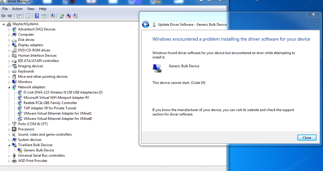
    1. I am unable to install the usb_dev_cserial.inf driver,I get the error "The INF file you selected does not support this method of installation".  I am

       using Windows 7. When I am manually installing the Drivers and after that when I am checking that driver installed properly or not, its showing

       "The device can not start Code 10". You can go through the below screenshot of device manger of 2 different PC's

    2. After dumping the code, in UART terminal last TEXT is showing "Waiting for HOST". 

    Thanks & Regards

    Anamika

  • Hello Anamika,

    Okay so this looks purely to be a Windows driver issue. This isn't an issue with your LaunchPad or the code you are loading in, or the power process.

    The only thing I can think of to try right now is give these older drivers from a pre-Windows 10 TivaWare release a try. Maybe they would work better with Windows 7. I don't expect this work as no other Win 7 users had issues with the latest drivers, but it's worth a try given you have had the issue on multiple PCs: windows_drivers.zip

  • Hii Ralph,

    I have downloaded the windows_drivers what you recommended, and replace that folder  with older windows_drivers.

    After plugin the launchpad with PC. its not showing any drivers is installing even its not showing to update the drivers.

    I have manually install the" usb_dev_bulk.inf " file ,still I am facing the same issue "The Device Can not Start (CODE 10)".

    I just want to clarify that, after plugin,  will it automatically update the drivers or we have to install it manually.

    If I have to install it manually, Kindly tell me the procedure.

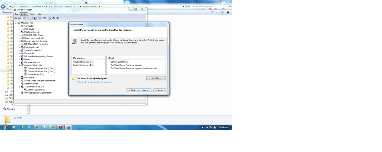
    This below procedure what I followed to install the drivers manually

    1.  Device Manager -> ACtion -> Add Legacy Hardware

    2.  Next -> Next -> Next -> Have Disk

    3. Then I selected the file "usb_dev_bulk.inf "(C:\ti\TivaWare_C_Series-2.1.4.178\windows_drivers)

    4. Then Click on OK after that below pop up is coming

    5. Next -> Next -> Finish

    Thanks & Regard

    Anamika

  • Hello Anamika,

    Sorry for the delay in reply, was on travel and this slipped through the cracks on me as a result, my apologizes as that is on me.

    That is not the steps I have used to install drivers.

    In Device Manager I right click the device that shows as not properly installed, and select "Update Drivers".

    That screen brings up two option, to Search Automatically for updated driver software OR to Browse my computer for driver software.

    Select the Browse option.

    From there, you can navigate to the TivaWare driver folder, and select it. Then click Next an Windows will try and install the drivers from that folder.

    See if that works.