This thread has been locked.

If you have a related question, please click the "Ask a related question" button in the top right corner. The newly created question will be automatically linked to this question.

CCS/MSP430G2230: Trying to load and debug via MSP-FET

Part Number: MSP430G2230
Other Parts Discussed in Thread: MSP-FET, MSP-EXP430G2ET, MSP430G2553

Tool/software: Code Composer Studio

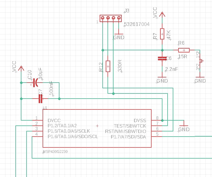
I assumed that we could programme and debug this device via Spy Bi-Wire (2 Wire JTAG).  We are using a MSP-FET emulator and have connected JTAG pins 1, 2, 7, 8 and 9:

JTAG Pin  JTAG Name    Target Name     Target Pin

1              TDO/TDI           SBWTDIO          6
2               VCC                 DVCC                1
7              TCK                  SBWTCK           7 (via 330R) 
8              TEST/VPP        TEST                 7
9               GND                 DVSS                8

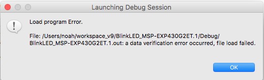
However, we can't get past even the most basic of tests ("Identify" fails and "Test Connection" is greyed out)

Is the "TI MSP USB1 (Default)" connection the right one for the MSP-FET.  I can't find anything else!

We have stripped back the target circuit components to the MSP430 and decoupling capacitors, but nothing helps.

Any suggestions?  What have we missed?

  • Hello Noah,
    the supply capacitors are certainly required for proper debugging communication and operation. What kind of HW do you use for the MSP430, is it a target socket board from TI or your own PCB?
    Did the MSP-FET you're using ever worked before?
    According to the tags you selected for your post you seem to be using CCS. Could you please import or setup the most simple blinking LED project example and try downloading the code by hitting the debug button?

    Best regards
    Peter
  • The HW is our own. We tried on the full circuit and then assembled a 'skeleton' with just the MCU and associated decoupling capacitors, 47K pull-up on RST and 300R in series with TCK.
    We don't have anything else on which to test the MSP-FET. The only other board around is a LaunchPad Kit (MSP-EXP430G2ET and I'm not sure if it's possible to connect the MSP-FET to that, especially if they are both plugged in to the same PC.
    We have run various blinking LED project examples on the LaunchPad Kit using our version of CCS, so we know that works through the LaunchPad interface.
    We have tried to download code via MSP-FET using all options available -- debug, run, debug targetConfig. They all fail with related issues -- they can't communicate with the target. With a new empty project, even "Identify" fails. With example projects, targetConfig never enables the Test Connection button (it's greyed out). With debug or run we get "a data verification error occurred, file load failed.
    It's something quite fundamental!
  • We'll get some wire jumpers tomorrow and try connecting the MSP-FET JTAG connector to individual pins on the LaunchPad. We'll disconnect the Launchpad USB and all the jumpers between host and target sections, so the target (MSP430G2553) will be powered by the MSP-FET. I'll let you know how we get on!
  • Hello Noah,
    not sure whether you have managed already running the test with the MSP-FET and the LaunchPad. That would be my recommendation, disconnecting the jumpers connecting the LaunchPad debugger section with the G2xx target. At the same jumper connections you can connect the MSP-FET by jumper wires, as you stated. This is a Spy-Bi-Wire connection, thus only VCC, GND, RST and TEST pin connections between the MSP-FET and the MSP device need to be established. This would be the same with your own prototype HW.
    If not yet managed to resolve the problem with your HW, could you please send me the schematics of the debug connections, you have applied with your prototype board and the MSP-FET?
    For further information on the required debug connections, you could use also the HW-Tools User's Guide www.ti.com/.../slau278ae.pdf

    Best regards
    Peter
  • Hi Peter

    I tested the MSP-FET on our LaunchPad board with just 4 wires -- Vcc (VCC-TOOL), Vss, SBWTDIO and SBWTCK. It loaded and ran without a problem.  Conclusion: the MSP-FET is working fine.

    I went back and retested our minimally populated board and I still get a failure to load (see attached).  By the way, the software is just a modified version of one of the example projects, adapted for our setup.  We haven't started verifying it since it doesn't even load, let alone run!

    I am attaching an extract from our schematic.  The only components on the test board are U1 (the MCU), C7 and C10 (power decoupling), R7 and C6 (RST decoupling) and R12 (SBWTCK protection).  To avoid any possible interference, no other components have been assembled. Only 4 wires are connected between the board and the MSP-FET -- Vcc (VCC-TOOL), Vss, SBWTDIO and SBWTCK -- and they are in a ribbon cable about 3 inches long.  We have checked end to end for continuity and shorts.

    In case it helps diagnosis, after CCS hangs we see "1" (~Vcc) on pins 6 and 7 of the MCU -- i.e. both SBW pins are high.

    Is it possible that the JTAG fuse has blown somehow? Can the CSS detect that or is there any other way to do so?  Would that give the same effect -- "file load failed"?

    Just casting around for any ideas . . .

    Thanks

    Noah

  • Hello Noah,

    I am afraid your Spy-Bi-Wire connections are wrong. As I have suggested in my last post, you can find the description of the required connections for Spy-Bi-Wire in the HW Tools User's Guide.

    Furthermore also the capacitor C6 is at the specified maximum value, which in dependency of the connection length and signal integrity conditions might be already beyond the acceptable limit.

    Please see Figure 2-2 in the HW Tools Users's Guide.

    Best regards

    Peter

  • Hi Peter
    Your feedback is much appreciated. However,I thought we had followed Fig 2-2 exactly:

    Vcc (VCC-TOOL): JTAG pin 2 -> MSP430G pin 1
    Vss: JTAG pin 9 ->MSP430G pin 8
    SBWTDIO: JTAG pin 1 -> MSP430G pin 6 (RST/NMI/SBWTDIO) 47K pull-up, 2.2nF decoupling
    SBWTCK: JTAG pin 7 -> MSP430G pin 7 (TEST/SBWTCK) via 330R resistor

    Please tell me from what you saw in our schematic which Spy-Bi-Wire connections are wrong. Maybe we're just too close to the design to spot errors that are obvious to new eyes.

    We'll try reducing C6 to see if that helps. We thought 2.2nF was the recommended, rather than maximum, value. I did try setting the communication speed to "slow" but it made no difference.

    Thanks
    Noah
  • Hi Peter
    So I finally noticed a line in the Console reporting a Data Verification error:
    "MSP430: File Loader: Verification failed: Values at address 0xC000 do not match Please verify target memory and memory map."
    Having read a bit more about Linker Command Files, I got suspicious about some of the files that had carried over from the example project we used as the starting point. I went back to the beginning and did a clean start project, copied some code into main.c and, hey presto, it works!!
    Thanks for giving us your time and attention.
    Regards
    Noah