This thread has been locked.

If you have a related question, please click the "Ask a related question" button in the top right corner. The newly created question will be automatically linked to this question.

CCS/CC3220S-LAUNCHXL: Debugging CC3220S using SWD

Part Number: CC3220S-LAUNCHXL
Other Parts Discussed in Thread: CC3220S, CC3220SF

Tool/software: Code Composer Studio

Hello,

I want to debug the CC3220S via two wire interface because I need to use the I2C interface via pin 16 &17. I can't use other pins because they're all used up because of a connected camera using the parallel camera interface.

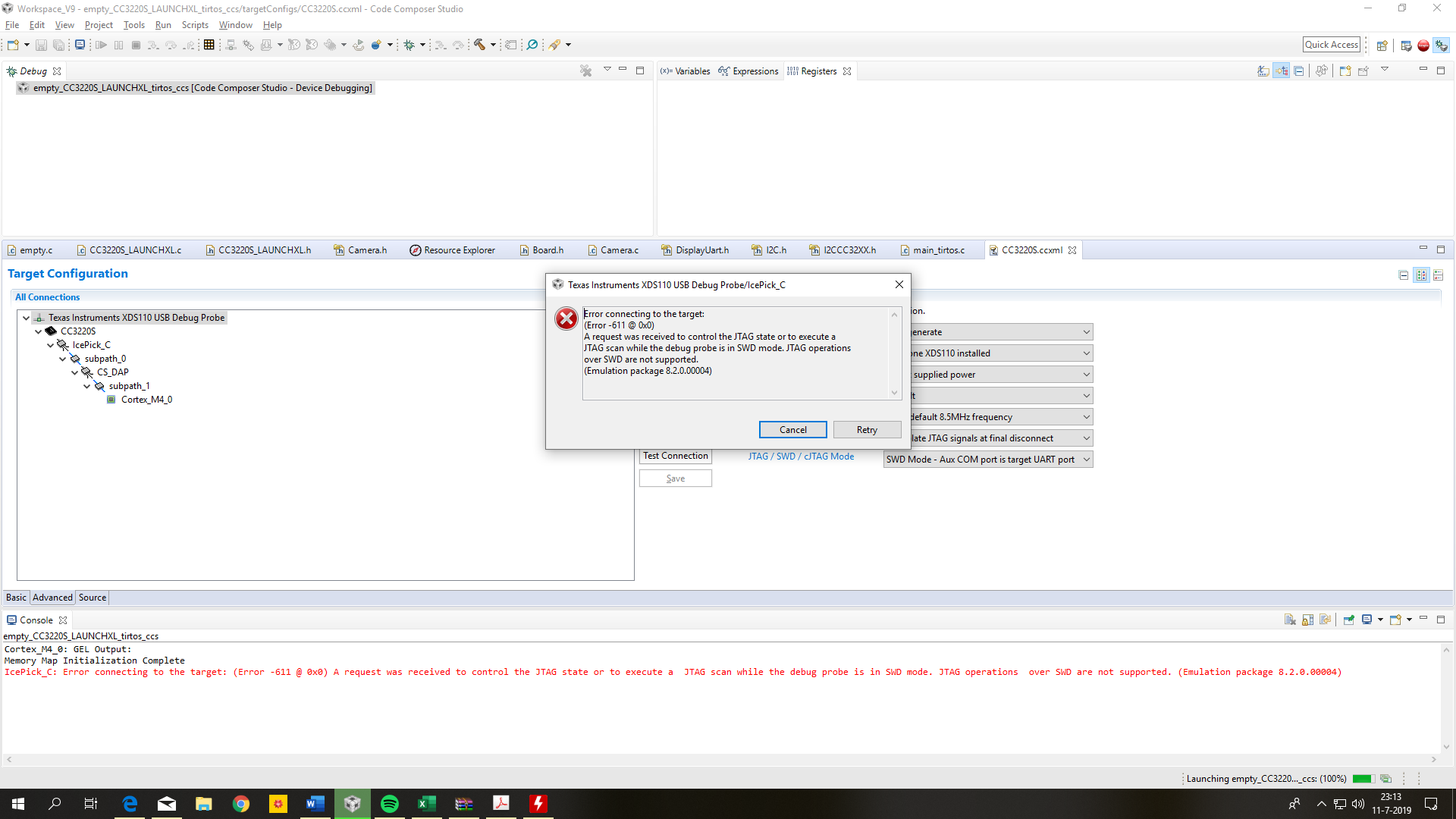
The datasheet of the CC3220S stated that for debugging there can be made use of SWD. Which will make Pin 16 & 17 available for I2C. Only the difficulty for me is to create this debugging method. In the picture below you can see the change I've made to the target configuration file. I've also switched the SOP (Sense On Power) pins to Binary 1 as stated in the launchpad user's guide page 15 : http://www.ti.com/lit/ug/swru463b/swru463b.pdf  .

The problem is that everytime I want to debug the CC3220S I get the error shown below.

I hope you can help me out.

Erwin

  • Hi,

    Unfortunately I can't reproduce this here, therefore I have a few comments:

    - Make sure the SOP jumpers are configured as shown below

    - Also, the Test Connection should return something like:

    Test Connection said:

    [Start: Texas Instruments XDS110 USB Debug Probe]

    Execute the command:

    %ccs_base%/common/uscif/dbgjtag -f %boarddatafile% -rv -o -S integrity

    [Result]


    -----[Print the board config pathname(s)]------------------------------------

    C:\Users\a0356111\AppData\Local\TEXASI~1\
    CCS\CCSV9_~3\0\0\BrdDat\testBoard.dat

    -----[Print the reset-command software log-file]-----------------------------

    This utility has selected a 100- or 510-class product.
    This utility will load the adapter 'jioxds110.dll'.
    The library build date was 'Jun 3 2019'.
    The library build time was '15:24:38'.
    The library package version is '8.2.0.00004'.
    The library component version is '35.35.0.0'.
    The controller does not use a programmable FPGA.
    The controller has a version number of '5' (0x00000005).
    The controller has an insertion length of '0' (0x00000000).
    This utility will attempt to reset the controller to enter SWD mode.

    -----[Print the reset-command hardware log-file]-----------------------------

    This emulator does not create a reset log-file.

    -----[Perform the SWD Mode Integrity test]-----------------------------------

    This test will read the IDCODE register 1 time.

    The IDCODE register value is 0x2ba01477.

    The SWD Mode Integrity test has succeeded.

    [End: Texas Instruments XDS110 USB Debug Probe]

    - When changing the SOP jumpers, make sure you power cycle the board to allow the device to sample these pins at power up. 

    Apart from this I can't think of any other issue related to the JTAG communications itself, but I will try to "break" my system here.

    Hope this helps,

    Rafael

  • Hi,

    I think I got it: I overlooked the device you selected. For SWD operations, you need to select the device with suffix _SWD (CC3220_SWD, CC3220S_SWD, CC3220SF_SWD) - in your particular case, select the device named CC3220S_SWD.

    I can reproduce the same error if I leave the device CC3220S selected in the Target Configuration and select the SWD protocol in the drop down menu. 

    Technically speaking, the CC32xx devices have a JTAG router called ICEPICK, which is not supported by the SWD protocol. In this case, when the tool detects that the ICEPICK is present in the scan chain configuration, it automatically selects the JTAG protocol, thus giving the error you saw. 

    I will perform a few additional investigations and probably file an enhancement request. 

    I apologize for the inconvenience,

    Rafael