This thread has been locked.

If you have a related question, please click the "Ask a related question" button in the top right corner. The newly created question will be automatically linked to this question.

CCS/TMDSLCDK6748:

Part Number: TMDSLCDK6748
Other Parts Discussed in Thread: TMS320C6748, TEST2

Tool/software: Code Composer Studio

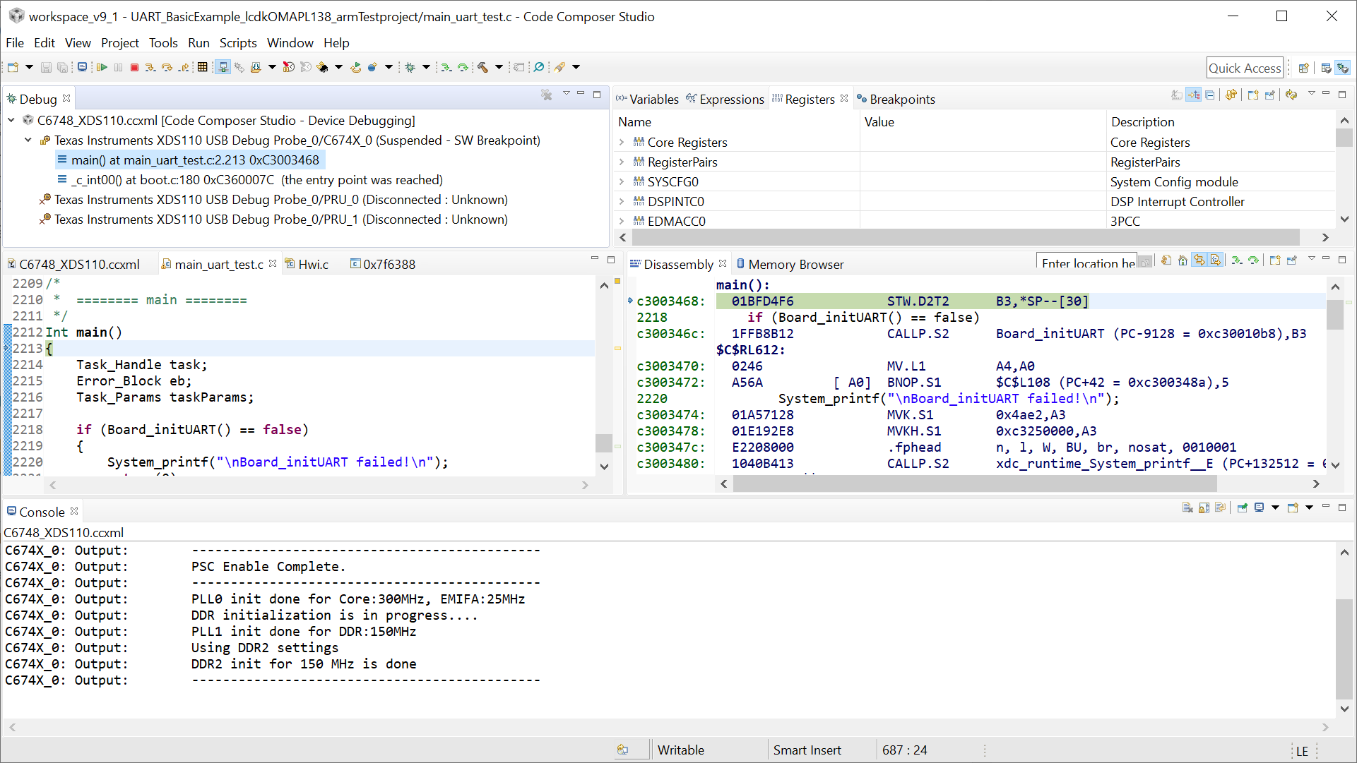
I'm working with a new TMS320C6748 DSP development Kit(LCDK) with an emulator XDS110 Debug Probe. Unfortunately, I can't get the setup to work as loading process gets failed while the compiler build the program with no errors, and I repeatedly get these errors associated with memory verification while I'm trying to load and debug the project on the Kit:

C674X_0: Trouble Reading Memory Block at 0x0 on Page 0 of Length 0x4: (Error -1176 @ 0x0) Unable to access device memory. Verify that the memory address is in valid memory. If error persists, confirm configuration, power-cycle board, and/or try more reliable JTAG settings (e.g. lower TCLK). (Emulation package 7.0.100.0)
C674X_0: File Loader: Verification failed: Target failed to read 0x00000000
C674X_0: GEL: File: C:\Users\14pg7\Documents\ELEC421_lab1_V13\adda\Debug\adda.out: Load failed.

Please help me in this regard.

  • Hi,

    Your executable has a misconfigured memory. Please check the reference Data Verification Errors below:

    http://software-dl.ti.com/ccs/esd/documents/troubleshooting-data_verification_errors.html 

    Hope this helps,

    Rafael

  • Thank you very much for your help.

    As it was recommended in the document you have linked me with, I have tried and added the required GEL files manually. Although some parts of the error has vanished, the main error persists.

    C674X_0: Output:  Target Connected.
    C674X_0: Output:  ---------------------------------------------
    C674X_0: Output:  Memory Map Cleared.
    C674X_0: Output:  ---------------------------------------------
    C674X_0: Output:  Memory Map Setup Complete.
    C674X_0: Output:  ---------------------------------------------
    C674X_0: Output:  PSC Enable Complete.
    C674X_0: Output:  ---------------------------------------------
    C674X_0: Output:  PLL0 init done for Core:300MHz, EMIFA:25MHz
    C674X_0: Output:  DDR initialization is in progress....
    C674X_0: Output:  PLL1 init done for DDR:150MHz
    C674X_0: Output:  Using DDR2 settings
    C674X_0: Output:  DDR2 init for 150 MHz is done
    C674X_0: Output:  ---------------------------------------------
    C674X_0: Trouble Writing Register PC: (Error -1176 @ 0x0) Unable to access device memory. Verify that the memory address is in valid memory. If error persists, confirm configuration, power-cycle board, and/or try more reliable JTAG settings (e.g. lower TCLK). (Emulation package 7.0.100.0)
    C674X_0: AutoRun: Target not run as the symbol "main" is not defined

  • Hi Rafael,

    Thank you very much for your help.

    As it was recommended in the document you have linked me with, I have tried and added the required GEL files manually. Although some parts of the error has vanished, the main error persists.

    C674X_0: Output:  Target Connected.
    C674X_0: Output:  ---------------------------------------------
    C674X_0: Output:  Memory Map Cleared.
    C674X_0: Output:  ---------------------------------------------
    C674X_0: Output:  Memory Map Setup Complete.
    C674X_0: Output:  ---------------------------------------------
    C674X_0: Output:  PSC Enable Complete.
    C674X_0: Output:  ---------------------------------------------
    C674X_0: Output:  PLL0 init done for Core:300MHz, EMIFA:25MHz
    C674X_0: Output:  DDR initialization is in progress....
    C674X_0: Output:  PLL1 init done for DDR:150MHz
    C674X_0: Output:  Using DDR2 settings
    C674X_0: Output:  DDR2 init for 150 MHz is done
    C674X_0: Output:  ---------------------------------------------
    C674X_0: Trouble Writing Register PC: (Error -1176 @ 0x0) Unable to access device memory. Verify that the memory address is in valid memory. If error persists, confirm configuration, power-cycle board, and/or try more reliable JTAG settings (e.g. lower TCLK). (Emulation package 7.0.100.0)
    C674X_0: AutoRun: Target not run as the symbol "main" is not defined

    Regards,

    Pourya

  • Pourya, 

    I was able to connect to the device without any problems and a code loaded to it yielded no errors. 

    In this case, is it possible to load an example project to the board? The Processor SDK has several C674x example projects built in. I am using the Processor SDK RTOS OMAPL138 version 5.01.00.11

    Also, how are the Boot switches on your board? On my working setup, the switches are set up like what is shown in Figure 2 of the C6748 LCDK User's Guide.

    Hope this helps,

    Rafael

    Hope this helps,

    Rafael

  • Dear Rafael,

    The DIP switches setup are the same here(the second and forth switches are ON), I'm also using a sample project for the test. This is the way I form a CCS project, please let me know if I'm doing anything wrong:

    1. A USB serial com is set with TeraTerm with 115200 as speed and every time I connect or reset the board the message: "BOOT Me" shows up

    2.CCS>Project>new project CCS, I couldn't fine any example project for dsk6748, however, I'm building an empty project and use one of the example files in the starter ware for this purpose.

    3. Then the libraries that are recommended for the LCDKc6748 are being included and the example file will be paste into the project work space:

    4. The target processor will be configured by associating the gel file, and the connection is being tested

    it is to mention that although the connection succeeds some parts are showing that the controller has no control over the process!

    [Start: Texas Instruments XDS110 USB Debug Probe]
    Execute the command:
    %ccs_base%/common/uscif/dbgjtag -f %boarddatafile% -rv -o -S integrity
    [Result]

    -----[Print the board config pathname(s)]------------------------------------
    C:\Users\14pg7\AppData\Local\TEXASI~1\CCS\
        ti\0\0\BrdDat\testBoard.dat
    -----[Print the reset-command software log-file]-----------------------------
    This utility has selected a 100- or 510-class product.
    This utility will load the adapter 'jioxds110.dll'.
    The library build date was 'Nov  6 2017'.
    The library build time was '10:36:36'.
    The library package version is '7.0.100.0'.
    The library component version is '35.35.0.0'.
    The controller does not use a programmable FPGA.
    The controller has a version number of '5' (0x00000005).
    The controller has an insertion length of '0' (0x00000000).
    This utility will attempt to reset the controller.
    This utility has successfully reset the controller.
    -----[Print the reset-command hardware log-file]-----------------------------
    The scan-path will be reset by toggling the JTAG TRST signal.
    The controller is the XDS110 with USB interface.
    The link from controller to target is direct (without cable).
    The software is configured for XDS110 features.
    The controller cannot monitor the value on the EMU[0] pin.
    The controller cannot monitor the value on the EMU[1] pin.
    The controller cannot control the timing on output pins.
    The controller cannot control the timing on input pins.
    The scan-path link-delay has been set to exactly '0' (0x0000).
    -----[Perform the Integrity scan-test on the JTAG IR]------------------------
    This test will use blocks of 64 32-bit words.
    This test will be applied just once.
    Do a test using 0xFFFFFFFF.
    Scan tests: 1, skipped: 0, failed: 0
    Do a test using 0x00000000.
    Scan tests: 2, skipped: 0, failed: 0
    Do a test using 0xFE03E0E2.
    Scan tests: 3, skipped: 0, failed: 0
    Do a test using 0x01FC1F1D.
    Scan tests: 4, skipped: 0, failed: 0
    Do a test using 0x5533CCAA.
    Scan tests: 5, skipped: 0, failed: 0
    Do a test using 0xAACC3355.
    Scan tests: 6, skipped: 0, failed: 0
    All of the values were scanned correctly.
    The JTAG IR Integrity scan-test has succeeded.
    -----[Perform the Integrity scan-test on the JTAG DR]------------------------
    This test will use blocks of 64 32-bit words.
    This test will be applied just once.
    Do a test using 0xFFFFFFFF.
    Scan tests: 1, skipped: 0, failed: 0
    Do a test using 0x00000000.
    Scan tests: 2, skipped: 0, failed: 0
    Do a test using 0xFE03E0E2.
    Scan tests: 3, skipped: 0, failed: 0
    Do a test using 0x01FC1F1D.
    Scan tests: 4, skipped: 0, failed: 0
    Do a test using 0x5533CCAA.
    Scan tests: 5, skipped: 0, failed: 0
    Do a test using 0xAACC3355.
    Scan tests: 6, skipped: 0, failed: 0
    All of the values were scanned correctly.
    The JTAG DR Integrity scan-test has succeeded.
    [End: Texas Instruments XDS110 USB Debug Probe]
    -------------------------------------------------------------------------

    5. I add a library from the 6000 family to the link order

    It is to note that if this library file is not being added I will get up to 22 errors at the building stage.

    6. Build All

    <Linking>
    warning #10211-D: cannot resolve archive C:/ti/ccsv7/tools/compiler/c6000_7.4.24/lib/libc.a to a compatible library, as no input files have been encountered
    warning #10062-D: entry-point symbol "_c_int00" undefined
    warning #10202-D: no suitable entry-point found; setting to 0
    'Finished building target: "UART_test2.out"'
     
    **** Build Finished ****

    7. Debug

    C674X_0: Output:  Target Connected.
    C674X_0: Output:  ---------------------------------------------
    C674X_0: Output:  Memory Map Cleared.
    C674X_0: Output:  ---------------------------------------------
    C674X_0: Output:  Memory Map Setup Complete.
    C674X_0: Output:  ---------------------------------------------
    C674X_0: Output:  PSC0 Enable Verify Timeout on Domain 0, LPSC 6
    C674X_0: Output:  PSC Enable Complete.
    C674X_0: Output:  ---------------------------------------------
    C674X_0: Output:  PLL0 init done for Core:300MHz, EMIFA:25MHz
    C674X_0: Output:  DDR initialization is in progress....
    C674X_0: Output:  PLL1 init done for DDR:150MHz
    C674X_0: Output:  Using DDR2 settings
    C674X_0: Output:  DDR2 init for 150 MHz is done
    C674X_0: Output:  ---------------------------------------------
    C674X_0: Trouble Writing Register PC: (Error -1176 @ 0x0) Unable to access device memory. Verify that the memory address is in valid memory. If error persists, confirm configuration, power-cycle board, and/or try more reliable JTAG settings (e.g. lower TCLK). (Emulation package 7.0.100.0)
    C674X_0: AutoRun: Target not run as the symbol "main" is not defined

    Thank you very much for your help in this regard.

    Regards,

    Pourya

  • Pourya, 

    I wouldn't use the GEL file from the Starterware package; if I recall correctly, it is severely outdated when compared to the one supplied by CCS. You can configure your target configuration file using the LCDKC6748 configuration, which already pre-populates the GEL file for you. 

    The BOOTME indicates the bootloader is set to serial mode. I don't think this should cause any connection problems. 

    Somehow I missed an important detail: the error is happening after the code is loaded. In this case, I would try to disable the Auto-Run to main, manually launch the debugger, load the code and execute the routine step-by-step from the code entry point _c_int00 to main. There is a chance the device is being reset right after the code is initialized. 

    To disable the Auto-Run to main, check section 7.2.5 of the CCS User's Guide below. 

    For a manual launch, check section 7.3.2 of the CCS User's Guide below. 

    http://software-dl.ti.com/ccs/esd/documents/users_guide/ccs_debug-main.html 

    To workaround this previous step, I would certainly try to load and run a known good example code. The Processor SDK I mentioned before is a more modern variant of the Starterware that may be more promising to work. 

    I will try to think about some additional scenarios and report back. 

    Hope this helps,

    Rafael