Other Parts Discussed in Thread: CCSTUDIO, UNIFLASH, CONTROLSUITE
Tool/software: Code Composer Studio
Hi,
I can connect to and program a secured TMS320F28377D using the XDS510 emulator, but following the exact same procedure with an XDS200 fails. I am currently using the DSAPI but the same problem happens using CCS directly.
Transcript using XDS510:
getServer: ENTRY sServerName: DebugServer.1
getServer: Getting definition for: DebugServer.1
getServer: Constructing server
getServer: RETURN com.ti.debug.engine.scripting.DebugServer@3772c4
setConfig: ENTRY sConfigurationFile: targetConfigs/TMS320F28377D-XDS510.ccxml
setConfig: RETURN
openSession: ENTRY sPattern: .+/C28xx_CPU1
start: ENTRY
start: Firing: onServerStarting()
start: Connecting to XPCOM DebugServer
start: Initializing DebugServer using specified configuration: "TMS320F28377D-XDS510.ccxml"
waitUntil: ENTRY com.ti.ccstudio.scripting.environment.ScriptingEnvironment@140d5f0 timeout: 500000 (ms)
<init>: CPU Name: C28xx_CPU1
<init>: PartNum: TMS320F28377D
<init>: Family: 320
<init>: SubFamily/MajorISA: 28
<init>: Revision/MinorISA: 127
<init>: Platform: EMULATOR
<init>: Processor ID: 1342219256
<init>: CPU Name: CPU1_CLA1
<init>: PartNum: TMS320F28377D
<init>: Family: 192
<init>: SubFamily/MajorISA: 20
<init>: Revision/MinorISA: 7
<init>: Platform: EMULATOR
<init>: Processor ID: 805339192
<init>: CPU Name: IcePick_C_0
<init>: PartNum: TMS320F28377D
<init>: Family: 240
<init>: SubFamily/MajorISA: 2
<init>: Revision/MinorISA: 0
<init>: Platform: NONE
<init>: Processor ID: 1006635013
waitUntil: RETURN com.ti.ccstudio.scripting.environment.ScriptingEnvironment@140d5f0
start: Firing: onServerStarted()
start: Searching for devices
listDevices: ENTRY
listDevices: Found debuggable device: Spectrum Digital XDS510USB Emulator_0/C28xx_CPU1
listDevices: Found debuggable device: Spectrum Digital XDS510USB Emulator_0/CPU1_CLA1
listDevices: Found non-debuggable device: Spectrum Digital XDS510USB Emulator_0/IcePick_C_0
listDevices: RETURN
start: RETURN
openSession: Searching for device exactly matching name: .+/C28xx_CPU1
openSession: No exact name matches found. Searching for device matching regular expression: .+/C28xx_CPU1
openSession: RETURN Spectrum Digital XDS510USB Emulator_0/C28xx_CPU1
setString: ENTRY ID: FlashEraseSelection Value: Entire Flash
setString: RETURN
Erasing entire flash
setString: ENTRY ID: VerifyAfterProgramLoad Value: Full verification
setString: RETURN
Performing *full* verification
Secure CPU
setString: ENTRY ID: Z1CSMPSWD0 Value: 0xXXXXXXXX
setString: RETURN
setString: ENTRY ID: Z1CSMPSWD1 Value: 0xXXXXXXXX
setString: RETURN
setString: ENTRY ID: Z1CSMPSWD2 Value: 0xXXXXXXXX
setString: RETURN
setString: ENTRY ID: Z1CSMPSWD3 Value: 0xXXXXXXXX
setString: RETURN
setBoolean: ENTRY ID: AllowInterruptsWhenHalted Value: true
setBoolean: RETURN
setBoolean: ENTRY ID: PoliteRealtimeMode Value: false
setBoolean: RETURN
setBoolean: ENTRY ID: AutoResetOnConnect Value: false
setBoolean: RETURN
setBoolean: ENTRY ID: ResetOnRestart Value: false
setBoolean: RETURN
connect: ENTRY
isConnected: ENTRY
isConnected: Target is not connected
isConnected: RETURN false
connect: Requesting target connect
waitUntil: ENTRY timeout: 500000 (ms)
C28xx_CPU1: GEL Output: OnTargetConnect
C28xx_CPU1: GEL Output:
Memory Map Initialization Complete
C28xx_CPU1: GEL Output: Unlock for ECSL (emulator)
C28xx_CPU1: GEL Output: SetupDCSM
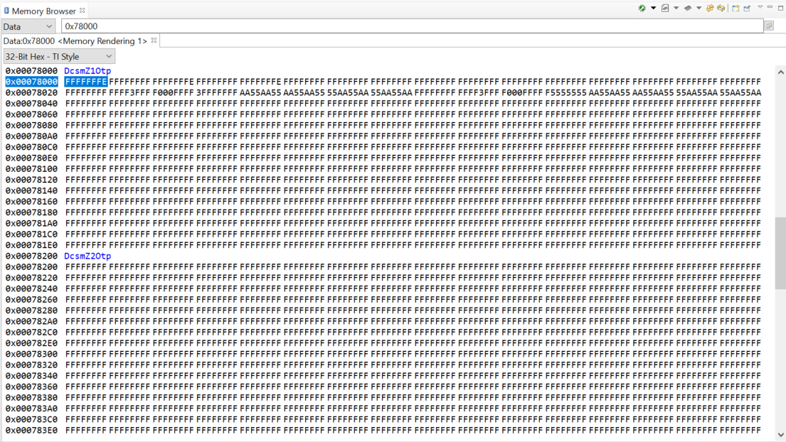
C28xx_CPU1: GEL Output: Z1_ZoneSelBlockPtr 0x00078020
C28xx_CPU1: GEL Output: Z2_ZoneSelBlockPtr 0x00078220
C28xx_CPU1: GEL Output: CSMKeyZ1 0 0xXXXXXXXX
C28xx_CPU1: GEL Output: CSMKeyZ1 1 0xXXXXXXXX
C28xx_CPU1: GEL Output: CSMKeyZ1 2 0xXXXXXXXX
C28xx_CPU1: GEL Output: CSMKeyZ1 3 0xXXXXXXXX
C28xx_CPU1: GEL Output: SetupDCSM
C28xx_CPU1: GEL Output: Z1_ZoneSelBlockPtr 0x00078020
C28xx_CPU1: GEL Output: Z2_ZoneSelBlockPtr 0x00078220
C28xx_CPU1: GEL Output: Reading CSMKey Zone1
C28xx_CPU1: GEL Output: CSMKeyZ1 0 0xXXXXXXXX
C28xx_CPU1: GEL Output: CSMKeyZ1 1 0xXXXXXXXX
C28xx_CPU1: GEL Output: CSMKeyZ1 2 0xXXXXXXXX
C28xx_CPU1: GEL Output: CSMKeyZ1 3 0xXXXXXXXX
C28xx_CPU1: GEL Output: Set CSMKey Zone1
C28xx_CPU1: GEL Output: Reading CSMKey Zone1
C28xx_CPU1: GEL Output: CSMKeyZ1 0 0xXXXXXXXX
C28xx_CPU1: GEL Output: CSMKeyZ1 1 0xXXXXXXXX
C28xx_CPU1: GEL Output: CSMKeyZ1 2 0xXXXXXXXX
C28xx_CPU1: GEL Output: CSMKeyZ1 3 0xXXXXXXXX
C28xx_CPU1: If erase/program (E/P) operation is being done on one core, the other core should not execute from shared-RAM (SR) as they are used for the E/P code. Also, CPU1 will be halted to determine SR ownership for the CPU which will run the Flash Plugin code, after which CPU1 will be set to run its application. User code execution from SR could commence after both flash banks are programmed.
log: Target is now connected
Transcript using XDS200:
getServer: ENTRY sServerName: DebugServer.1
getServer: Getting definition for: DebugServer.1
getServer: Constructing server
getServer: RETURN com.ti.debug.engine.scripting.DebugServer@3772c4
setConfig: ENTRY sConfigurationFile: targetConfigs/TMS320F28377D-XDS200.ccxml
setConfig: RETURN
openSession: ENTRY sPattern: .+/C28xx_CPU1
start: ENTRY
start: Firing: onServerStarting()
start: Connecting to XPCOM DebugServer
start: Initializing DebugServer using specified configuration: "C:\Development\Tesla\Main\Tools\DSPProgram\targetConfigs\TMS320F28377D-XDS200.ccxml"
waitUntil: ENTRY com.ti.ccstudio.scripting.environment.ScriptingEnvironment@140d5f0 timeout: 500000 (ms)
<init>: CPU Name: C28xx_CPU1
<init>: PartNum: TMS320F28377D
<init>: Family: 320
<init>: SubFamily/MajorISA: 28
<init>: Revision/MinorISA: 127
<init>: Platform: EMULATOR
<init>: Processor ID: 1342219256
<init>: CPU Name: CPU1_CLA1
<init>: PartNum: TMS320F28377D
<init>: Family: 192
<init>: SubFamily/MajorISA: 20
<init>: Revision/MinorISA: 7
<init>: Platform: EMULATOR
<init>: Processor ID: 805339192
<init>: CPU Name: IcePick_C_0
<init>: PartNum: TMS320F28377D
<init>: Family: 240
<init>: SubFamily/MajorISA: 2
<init>: Revision/MinorISA: 0
<init>: Platform: NONE
<init>: Processor ID: 1006635013
waitUntil: RETURN com.ti.ccstudio.scripting.environment.ScriptingEnvironment@140d5f0
start: Firing: onServerStarted()
start: Searching for devices
listDevices: ENTRY
listDevices: Found debuggable device: Texas Instruments XDS2xx USB Debug Probe_0/C28xx_CPU1
listDevices: Found debuggable device: Texas Instruments XDS2xx USB Debug Probe_0/CPU1_CLA1
listDevices: Found non-debuggable device: Texas Instruments XDS2xx USB Debug Probe_0/IcePick_C_0
listDevices: RETURN
start: RETURN
openSession: Searching for device exactly matching name: .+/C28xx_CPU1
openSession: No exact name matches found. Searching for device matching regular expression: .+/C28xx_CPU1
openSession: RETURN Texas Instruments XDS2xx USB Debug Probe_0/C28xx_CPU1
setString: ENTRY ID: FlashEraseSelection Value: Entire Flash
setString: RETURN
Erasing entire flash
setString: ENTRY ID: VerifyAfterProgramLoad Value: Full verification
setString: RETURN
Performing *full* verification
Secure CPU
setString: ENTRY ID: Z1CSMPSWD0 Value: 0xXXXXXXXX
setString: RETURN
setString: ENTRY ID: Z1CSMPSWD1 Value: 0xXXXXXXXX
setString: RETURN
setString: ENTRY ID: Z1CSMPSWD2 Value: 0xXXXXXXXX
setString: RETURN
setString: ENTRY ID: Z1CSMPSWD3 Value: 0xXXXXXXXX
setString: RETURN
setBoolean: ENTRY ID: AllowInterruptsWhenHalted Value: true
setBoolean: RETURN
setBoolean: ENTRY ID: PoliteRealtimeMode Value: false
setBoolean: RETURN
setBoolean: ENTRY ID: AutoResetOnConnect Value: false
setBoolean: RETURN
setBoolean: ENTRY ID: ResetOnRestart Value: false
setBoolean: RETURN
connect: ENTRY
isConnected: ENTRY
isConnected: Target is not connected
isConnected: RETURN false
connect: Requesting target connect
waitUntil: ENTRY timeout: 500000 (ms)
SEVERE: C28xx_CPU1: Error connecting to the target: (Error -1133 @ 0x0) Device blocked debug access because it is currently executing non-debuggable code. You may retry after the device has had time to enter debuggable code, or you may cancel, disable realtime mode, and then attempt to connect. (Emulation package 8.0.27.9)
log: Error when connecting to target
waitUntil: RETURN
isConnected: ENTRY
isConnected: Target is not connected
isConnected: RETURN false
SEVERE: emulation failure occurred
SEVERE: Error connecting to the target: emulation failure occurred
Programming Error JavaException: com.ti.ccstudio.scripting.environment.ScriptingException: Error connecting to the target: emulation failure occurred
terminate: ENTRY
terminate: Firing: onSessionTerminating()
terminate: Unregistering this session from the DebugServer
terminate: Firing: onSessionTerminated()
disposeAndUnload: Firing: onServerStopping()
disposeAndUnload: Stopping DebugServer
waitUntil: ENTRY com.ti.ccstudio.scripting.environment.ScriptingEnvironment@140d5f0 timeout: 500000 (ms)
terminate: ENTRY
terminate: RETURN
terminate: ENTRY
terminate: RETURN
terminate: ENTRY
terminate: RETURN
waitUntil: RETURN com.ti.ccstudio.scripting.environment.ScriptingEnvironment@140d5f0
disposeAndUnload: Firing: onServerStopped()
terminate: RETURN
stop: ENTRY
stop: RETURN
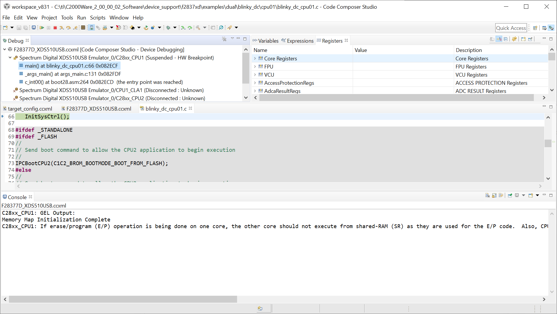
Both ccxml files point to the same gel script that unlocks zone 1, this can be seen executing when using an XDS510 but not when using an XDS200. The gel script is read when using an XDS200 but it just does not seem to run.
The session options are identical between the two emulators save for the 'HaltOnConnect' boolean which is false (and unsettable) for the XDS510 but true for the XDS200, setting this to false for the XDS200 makes no difference.
The same JS code is run for both examples, just the config file (ccxml) is different.
Therefore, is there an issue with gel scripts with the XDS200? Or is something else going on?
Thanks,
Richard.