


Tool/software: Code Composer Studio
To whom it may concern,
I want to use EK_TM4C1294XL for controlling a high frequency power inverter. I wanted to run some example codes that I have downloaded from the original website of TI. I need some assistance to solve some problems related to Code Composer Studio.
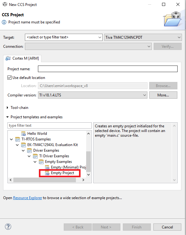
I created an Empty Project in TI-RTOS Example. After that, I have composed a program that simulates a PWM Module. However, I would like to change the system clock setting (Clock_tickPeriod) due to the working principles of the Task_sleep() function that changes the current task's mode from Mode_RUNNING to Mode_BLOCKED, and delays its execution for nticks increments of the system clock, where the actual time delayed can be up to 1 system clock tick less than nticks due to granularity in system timekeeping and the time elapsed per tick is determined by Clock_tickPeriod. So, how can I declare a value for Clock_tickPeriod?
Secondly, I have created two pulse generators that do not work at the same time but 1280 ns apart from each other. How can I synchronize these two pulse generators to get output at the same time?
Moreover, I have created a while-loop , which can be seen down below, that includes two GPIO_toggle () functions. Is it possible to combine these functions into one?
while (1) {
GPIO_toggle(Board_LED0);
Task_sleep((float)arg0);
GPIO_toggle(Board_LED1);
}
I kindly request your imminent assistance to solve this issue, which I'm on a deadline for.
I am sharing the codes below:
/*
 * Copyright (c) 2015, Texas Instruments Incorporated
 * All rights reserved.
 *
 * Redistribution and use in source and binary forms, with or without
 * modification, are permitted provided that the following conditions
 * are met:
 *
 * *  Redistributions of source code must retain the above copyright
 *    notice, this list of conditions and the following disclaimer.
 *
 * *  Redistributions in binary form must reproduce the above copyright
 *    notice, this list of conditions and the following disclaimer in the
 *    documentation and/or other materials provided with the distribution.
 *
 * *  Neither the name of Texas Instruments Incorporated nor the names of
 *    its contributors may be used to endorse or promote products derived
 *    from this software without specific prior written permission.
 *
 * THIS SOFTWARE IS PROVIDED BY THE COPYRIGHT HOLDERS AND CONTRIBUTORS "AS IS"
 * AND ANY EXPRESS OR IMPLIED WARRANTIES, INCLUDING, BUT NOT LIMITED TO,
 * THE IMPLIED WARRANTIES OF MERCHANTABILITY AND FITNESS FOR A PARTICULAR
 * PURPOSE ARE DISCLAIMED. IN NO EVENT SHALL THE COPYRIGHT OWNER OR
 * CONTRIBUTORS BE LIABLE FOR ANY DIRECT, INDIRECT, INCIDENTAL, SPECIAL,
 * EXEMPLARY, OR CONSEQUENTIAL DAMAGES (INCLUDING, BUT NOT LIMITED TO,
 * PROCUREMENT OF SUBSTITUTE GOODS OR SERVICES; LOSS OF USE, DATA, OR PROFITS;
 * OR BUSINESS INTERRUPTION) HOWEVER CAUSED AND ON ANY THEORY OF LIABILITY,
 * WHETHER IN CONTRACT, STRICT LIABILITY, OR TORT (INCLUDING NEGLIGENCE OR
 * OTHERWISE) ARISING IN ANY WAY OUT OF THE USE OF THIS SOFTWARE,
 * EVEN IF ADVISED OF THE POSSIBILITY OF SUCH DAMAGE.
 */

/*
 *  ======== empty.c ========
 */
/* XDCtools Header files */
#include <xdc/std.h>
#include <xdc/runtime/System.h>

/* BIOS Header files */
#include <ti/sysbios/BIOS.h>
#include <ti/sysbios/knl/Task.h>

/* TI-RTOS Header files */
// #include <ti/drivers/EMAC.h>
#include <ti/drivers/GPIO.h>
#include <ti/drivers/PWM.h>
#include <ti/drivers/PWM.c>
// #include <ti/drivers/I2C.h>
// #include <ti/drivers/SDSPI.h>
// #include <ti/drivers/SPI.h>
#include <ti/drivers/UART.h>
// #include <ti/drivers/USBMSCHFatFs.h>
// #include <ti/drivers/Watchdog.h>
// #include <ti/drivers/WiFi.h>

/* Board Header file */
#include "Board.h"

#define TASKSTACKSIZE   512
Task_Struct task0Struct;
Char task0Stack[TASKSTACKSIZE];

/*
 *  ======== heartBeatFxn ========
 *  Toggle the Board_LED0. The Task_sleep is determined by arg0 which
 *  is configured for the heartBeat Task instance.
 */


Void heartBeatFxn(UArg arg0, UArg arg1)
{

    while (1) {


        GPIO_toggle(Board_LED0);
        Task_sleep((float)arg0);
        GPIO_toggle(Board_LED1);

    }
}


/*
 *  ======== main ========
 */
int main(void)
{

    Task_Params taskParams;
    /* Call board init functions */
    Board_initGeneral();
    // Board_initEMAC();
    Board_initGPIO();
    Board_initPWM();
    // Board_initI2C();
    // Board_initSDSPI();
    // Board_initSPI();
     Board_initUART();
    // Board_initUSB(Board_USBDEVICE);
    // Board_initUSBMSCHFatFs();
    // Board_initWatchdog();
    // Board_initWiFi();

    /* Construct heartBeat Task  thread */
    Task_Params_init(&taskParams);
    taskParams.arg0 = 1;
    taskParams.stackSize = TASKSTACKSIZE;
    taskParams.stack = &task0Stack;
    Task_construct(&task0Struct, (Task_FuncPtr)heartBeatFxn, &taskParams, NULL);


     /* Turn on user LED */
    //GPIO_write(Board_PWM0, Board_LED_ON );
    //GPIO_write(Board_PWM1, Board_LED_ON );
    System_printf("Starting the example\nSystem provider is set to SysMin. "
                           "Halt the target to view any SysMin contents in ROV.\n");
    /* SysMin will only print to the console when you call flush or exit */
    System_flush();

    /* Start BIOS */
    BIOS_start();

    return (0);
}
