This thread has been locked.

If you have a related question, please click the "Ask a related question" button in the top right corner. The newly created question will be automatically linked to this question.

CCS/TMDSEMU100V2U-14T: OnTargetConnect() errors

Part Number: TMDSEMU100V2U-14T
Other Parts Discussed in Thread: OMAP-L138, OMAPL138, AM1808, TMDSEMU560V2STM-UE, TMDSEMU560V2STM-U, TMDSEMU200-U, TMDSEMU110-U

Tool/software: Code Composer Studio

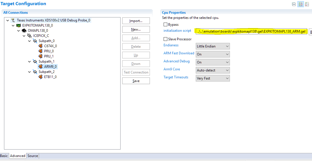
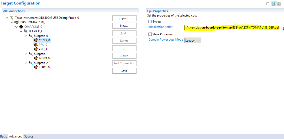
I'm trying to debug an Experimenter OMAP-L138 board, using CCS (version 9.2.0.00013) and an XDS100v2 probe <with updated firmware>. But I keep getting the dreaded "OnTargetConnect()" error. (Though the target configuration <.ccxml> "test connection" always goes successfully.) Is there a recommended way to solve this problem?

*************************

I did my due diligence homework, and searched for the answer myself. But many of the TI Wiki links on this issue seem to dead-end, and I'm seeing some confusing info. I recall one attempt involved setting the JTAG clock (TCLK) to "Adaptive with user specified limit" and setting that limit to a lower frequency. (I tried many lower frequencies, and it didn't work.) Another attempt involved getting rid of the .gel file, and instead just initialize the board via the program code. (I would need instructions on how to do that.) Another attempt involved upgrading to the newer XDS110 probe, but the product-page says this probe does not support the OMAP-L138. Likewise the XDS200 probe product-page does not list the OMAP-L138 as a supported device. What am I missing?

Here is the error I keep getting:


ARM9_0: GEL: Error while executing OnTargetConnect(): Page fault occurred reading 0x01C10800
at (*((unsigned int *) ((0x01C10000+0x800)+(4*LPSC_num)))&0x1F) [EXPKITOMAPL138_ARM.gel:939]
at PSC0_LPSC_enable(0, 0) [EXPKITOMAPL138_ARM.gel:492]
at PSC_All_On_Experimenter() [EXPKITOMAPL138_ARM.gel:251]
at OnTargetConnect()
ARM9_0: Trouble Writing Memory Block at 0x800050f0 on Page 0 of Length 0x168
ARM9_0: File Loader: Verification failed: Target failed to write 0x800050F0
ARM9_0: GEL: File: C:\<... path_name>\Debug\<program_name>.out: Load failed.
ARM9_0: Unable to terminate memory download: NULL buffer pointer at 0x320

Thanks for your help.

  • Hi,

    Unfortunately I don't have my OMAPL138 kit with me to throroughly validate this, but I wonder if there is an arrangement of DIP switches that may be failing to allow you to connect to the board. That or pre-existing Linux/u-boot stored in the board's memory that may be causing several registers from being accessed. 

    The DIP switch configuration can be found in the experimenter's kit User's Guide available at the LogicPD website at:

    https://support.logicpd.com/ProductDownloads/OMAP-L138SOM-M1(eXperimenterKit).aspx

    Indeed the Debug Probe configuration has to be set to Adaptive clocking (The ARM9 core requires it), but it is set by default when you create a new target configuration file. 

    Also, the XDS200 page should mention the OMAPL family of devices there. Sorry about the oversight. 

    Hope this helps,

    Rafael

  • Rafael,

    Thanks for your help, though the problem isn't solved yet.

    The OMAP family is explicitly "not supported" on the new XDS110 probe product-page, and that might likely explain why my older XDS100v2<with updated firmware> hasn't solved the connection problem.

    I'm positive my DIP switches are correctly set. (Dip Switches 5 & 8 are on, and the rest are off.) Also, this is the second Experimenter OMAP-L138 board I am trying, and the same problem recurs. I had the same problem (OnTargetConnect) repeatedly with the first board, and all my solution attempts failed. So I popped open a new (unused, fresh out of the box) board, and tried again. Still no luck. (So there shouldn't be anything unusual about pre-existing code stored in the board's memory. On the other hand, if pre-existing code on a new board is the problem, then shouldn't that be on a TI Wiki page somewhere?).

    I am tempted to just order the XDS200 probe (~$300), but I'm not confident that will solve the problem. I am not confident partly because the OMAP family is not listed as a "supported" device on the XDS200 product page. But I'm also not confident because the OnTargetConnect issue recurs so often on the forum, with no solution given in the TI Wiki pages. Something is awry. The solutions seem unsure, wandering, and not-confident. Is there a confident solution? A solid recommendation?

    Thanks again for your help.

  • Hi,

    Walter Snafu said:
    The OMAP family is explicitly "not supported" on the new XDS110 probe product-page, and that might likely explain why my older XDS100v2<with updated firmware> hasn't solved the connection problem.

    The two Debug Probe technologies are quite different - the XDS100 supports the legacy Adaptive Clocking mechanism. The description of your problem is congruent with the scenario where adaptive is not configured (or not supported, in case of XDS110). Which debug probe are you trying to use when the issue happens, and how it is configured? Fixed or Adaptive clock? 

    Walter Snafu said:
    I'm positive my DIP switches are correctly set. (...) On the other hand, if pre-existing code on a new board is the problem, then shouldn't that be on a TI Wiki page somewhere?).

    I don't recall how these boards came out of factory, but the arrangement of DIP switches matches the EMU Debug mode on the User's Guide and therefore pre-existing code shouldn't be a problem. This was documented somewhere, but since this board was discontinued a while ago there is a possibility the documentation may have been removed. I would have to defer an exact reason to the device maintainers. 

    Walter Snafu said:
    (...) But I'm also not confident because the OnTargetConnect issue recurs so often on the forum, with no solution given in the TI Wiki pages. Something is awry. The solutions seem unsure, wandering, and not-confident. Is there a confident solution? A solid recommendation?

    The XDS100v2 you have and the XDS200 support Adaptive Clocking if configured to do so on the Target Configuration File. The reason why you would want to get a XDS200 is a massive improve in debugging and code load performance when compared to the XDS100v2. These two probes have been used with he OMAPL138 for years without issues. 

    The reason why some of the discussions can be vague is due to the nature of the problems. The Debug Probes only have so much visibility about the target status and can be fooled in various ways, especially if they involve hardware issues or misconfigurations. In this particular case (adaptive vs fixed clocking), the problem only happens during modifications to the PLL as explained in this post. Otherwise, everything works fine. 

    Hope this helps,

    Rafael

  • Rafael
    the XDS100 supports the legacy Adaptive Clocking mechanism. ... Which debug probe are you trying to use when the issue happens, and how it is configured? Fixed or Adaptive clock? 

    I'm using the XDS100v2 <with updated firmware>. I have it configured to use the Adaptive clock, and I've tried setting the limit at many different frequencies. (I tried 100kHz, and 500kHz, and 1MHz, and many other frequencies).  I also tried configuring it at a "fixed" clock.  The "Test connection" always succeeds, but nonetheless it doesn't connect or let me examine registers, or load the program, or debug. Something is awry. 

    TI used to have Wiki pages for the Omap-L138, that stepped us through the process of connecting to target boards, and debugging multi-processors (ARM and DSP), etc. But those Wiki pages have disappeared. They were useful, so why have they disappeared?  They would be handy at a time like this. 

    Rafael
    the arrangement of DIP switches matches the EMU Debug mode on the User's Guide and therefore pre-existing code shouldn't be a problem.

    Right. I am confident the DIP switches are set correctly, for the EMU Debug mode. (I have the original setup documents for the board.)

    Rafael
    The reason why you would want to get a XDS200 is a massive improve in debugging and code load performance when compared to the XDS100v2.

    It sounds like my XDS100v2 should connect and debug, (and that I shouldn't need the XDS200, unless I need a massive improvement in debugging and code load performance). I'm still baffled why my XDS100v2 isn't connecting.  

    Rafael
    In this particular case (adaptive vs fixed clocking), the problem only happens during modifications to the PLL as explained in this post. Otherwise, everything works fine. 

    I watched the video in that post, and did what it suggested. But I could not set the "value" of the expressions, (apparently, because of lack of connection to the target board). Again, it always passes the "Test connection" successfully, but doesn't allow me to do anything else.

    Thank you for any help you may give.

  • Walter,

    I asked for the device owners to comment about the removed wiki pages - they may have moved these references somewhere else. 

    Back to the connection issue, at this point I can't really imagine what is happening in your setup. 

    If anything is behaving poorly on the host, perhaps try different USB cables and port, or an entirely different host?  

    Another angle is to have issues with the stabilty of the connection itself. The reason is that the Test Connection sends short bursts of data and therefore any possible interferences (crosstalk, GND noise, etc.) may not have enough time to manifest and disrupt the data stream. 

    From a command line you can try to issue the dbgjtag integrity test command but repeating it indefinitely. While it runs, you can wiggle cables, connections, the SOM module (there was a case where the SOM was not properly seated) and see if there is a breakdown at a given point. 

    The location of the utility and the command are:

    C:\ti\ccs920\ccs\ccs_base\common\uscif>dbgjtag -f @xds100v2 -S integrity,repeat=0

    Apart from this, I am running out of ideas as to why the XDS100v2 is not working. I will report back if I find anything. 

    Hope this helps,

    Rafael

  • Rafael,

    I've had a breakthrough.

    My OMAP-L138 project software currently focuses only on the ARM (to handle the USB stuff). And when I try to load/debug this project, the load fails (with the error I described previously). But if I deselect the project, and connect "manually"(?), then the connection works, and I can read the (DSP?) processor registers. So something about the connection is working here. I now believe the problem is not with my XDS100v2 probe.  

    Instead, my difficulty involves debugging with CCS on the multicore nature of the OMAP processor. There are some tricks involved, and it's not obvious how to proceed. There used to be Wiki pages on this stuff -- I've searched -- but I cannot locate them now. Can you direct me to a resource/Wiki for solving this?

    Thanks again for your help.

  • Walter,

    Walter Snafu said:
    My OMAP-L138 project software currently focuses only on the ARM (to handle the USB stuff). And when I try to load/debug this project, the load fails (with the error I described previously). But if I deselect the project, and connect "manually"(?), then the connection works, and I can read the (DSP?) processor registers. So something about the connection is working here. I now believe the problem is not with my XDS100v2 probe. 

    That would be somewhat expected, as the DSP is probably not running any GEL routine. Given that you are able to connect, can you load code or perhaps simply perform a memory load with a random file? That would rule out any minor stability issues. 

    If you are able to load code, can you send the .ccxml file you are using to connect to the device? I am suspicious of a minor configuration detail. 

    Regards,

    Rafael

  • Walter

    In general we are moving migrating relevant content from wikis and deleting content that is stale or not up to date. 

    I am not sure which wiki you were referring to, but please see if this was the link and content

    If this was not it, than I would need you to provide the specific link that you used to previously rely on.

    Regards

    Mukul 

  • Rafael,

    I'm using the .ccxml file that CCSv9 creates for me automatically, (when I specify my "Experimenter OMAP-L138 board" in the project properties). (Though I've also tried many variants of it, with no success.)

    ******

    Here is the OMAP-L138 debug process, using CCSv9, as I currently understand it. (This info comes from this file, together with my updating it with the changes that have occurred since CCSv4. As you can see, it is unlikely for a user to stubble across this sequence of actions without some help. 

    View -> Target Configurations
    Switch to Target Configurations window, and select the proper target configuration
    <right-click> -> Launch Selected Configuration

    Switch to Debug window
    Select the target configuration
    <right-click> -> Show All Cores
    Expand the target configuration to see all the cores
    Select the ARM core
    <right-click> -> Connect Target
        (That is where I get an OnTargetConnect error)

    Scripts -> Wake Core -> Wake_DSP
    Select DSP core
    <right-click> -> Connect Target

    Select the proper core for your program.
    Run -> Load -> Load Program -> Select your program to load
        That again is where the program load fails, with the OnTargetConnect error

    ******

    In this file, they recommend the following "preferred" solution to the OnTargetConnect error:

    Setup the PLL by executing code (ex: UBoot, etc.) instead of using the GEL file. (preferred)

    I would need instructions on how to do that. I have no idea where to begin that.

  • I tried lots of things to find clues. Here are some clues, that I hope can lead to a solution, (unable to load/debug programs on the OMAP-L138 ARM).

    1) The XDS100v2 probe <with updated firmware> works fine, and allows reading & writing the registers of the DSP and ARM. So, the probe does not seem to be the problem.

    2) The problem occurs when the ARM.gel runs, but not when the DSP.gel runs. The error is:
    ARM9_0: GEL: Error while executing OnTargetConnect(): Page fault occurred reading 0x01C10800
    at (*((unsigned int *) ((0x01C10000+0x800)+(4*LPSC_num)))&0x1F) [EXPKITOMAPL138_ARM.gel:939]
    at PSC0_LPSC_enable(0, 0) [EXPKITOMAPL138_ARM.gel:492]
    at PSC_All_On_Experimenter() [EXPKITOMAPL138_ARM.gel:251]
    at OnTargetConnect()

    3) That error occurs when menu Scripts -> PSC_All_On_Experimenter is run on the ARM, but not when that script is run on the DSP. (This routine occurs within both the ARM.gel, and within the DSP.gel.) So the problem seems to occur within the ARM.gel file, apparently within the PSC_All_On_Experimenter routine. The error occurs in a subroutine "PSC0_LPSC_enable()", which initializes the Power and Sleep Controller, the clocks, and phase-locked loops.

    4) The presence (or not) of the DSP.gel within the target configuration (.ccxml), has no effect on the above problem, either way.

    5) If the ARM.gel is removed from the target configuration (.ccxml), then the error doesn't occur when launching the .ccxml. But then is the ARM properly initialized, if it doesn't have a .gel?

    6) When the ARM.gel is either present or absent from the .ccxml, (and the DSP.gel is present), then the following error occurs when a program is loaded onto the ARM.

    ARM9_0: Trouble Writing Memory Block at 0x800050f0 on Page 0 of Length 0x168
    ARM9_0: File Loader: Verification failed: Target failed to write 0x800050F0
    ARM9_0: GEL: File: C:\<project_path>\Debug\<project_name>.out: Load failed.
    ARM9_0: Unable to terminate memory download: NULL buffer pointer at 0x320

    I hope this helps find a solution.

  • By much trial-and-error, I found a way to bring up both OMAP-L138 cores (DSP & ARM), without CCSv9 generating any error messages. At that point, both cores are connected, and have their memory maps loaded, and all the registers (from both cores) can be read and written. The DSP is fully usable and debuggable. So far, so good. But CCS generates error messages when loading a program to the ARM, so ARM programs cannot yet be run or debugged.

    Perhaps that is a step forward? <perhaps...>

    Here is how that is accomplished.

    I created a new version of the ARM .gel file. (I call it ARM.gel) In this version, go to the routine OnTargetConnect() and within it, comment out three subroutine calls, like this:

    OnTargetConnect( )
    {
    Clear_Memory_Map();
    Setup_Memory_Map();

    // PSC_All_On_Experimenter();
    // Core_300MHz_mDDR_150MHz();
    // Wake_DSP();
    }

    Those three subroutines cause CCSv9 to complain when trying to connect to the ARM, (so that is why we comment them out.) The purpose of those three subroutines will be accomplished instead by the DSP .gel. (The DSP .gel runs PSC_All_On_Experimenter() and then Core_300MHz_mDDR_150MHz().

    Edit the target configuration (.ccxml) to use the new ARM.gel, and make ARM the "slave" to the DSP.) And Save the .ccxml

    Then connect to the board, like this:

    View -> Target Configurations,
    select the target configuration (.ccxml),
    <right-click> Launch Selected Configuration

    Switch to the Debug window.
    Select the .ccxml
    <right-click> Show all cores
    Expand the list of cores under the .ccxml

    Select the DSP core (C674X_0)
    <right-click> Connect Target
    (Note: This will run the DSP .gel, and connect to the DSP)

    Menu Scripts -> Wake Core -> Wake_ARM

    Select the ARM core
    <right-click> Connect Target
    (Note: This will run the ARM.gel), and connect to the ARM)

    At this point, you can read/write all registers on both cores, and view their entire memory map.

    But unfortunately, loading a program to the ARM still causes an error, so it cannot be run or debugged.

    That seems to be a step forward. Any clues on what to try next?

  • Hi Walter,

    Could you please try creating a new target configuration and selecting "EXPKITOMAPL138" as the Board or Device, as shown below?

    This will auto-populate the target configuration with the necessary GEL files bundled with CCS for both the ARM and DSP core:

    After saving, open the target configurations window and right-click on this target configuration and select "Launch Selected Configuration." You should then be able to connect to the ARM (need to always connect to the ARM first) and then DSP.

    This should work as-is, you shouldn't need to make any modifications to the GEL files. If this doesn't work, it most likely indicates a hardware issue.

    Hope this helps. Please let us know how it goes.

    Regards,
    Sahin

  • Sahin,

    Thank you for your help, and your careful instructions. I did exactly as you described, (which is also what I had tried previously). CCSv9 generated the same "OnTargetConnect()" error as before. (See above.)

    However, I noticed something I hadn't noticed before, (though it was probably there before). That is, despite the so-called "OnTargetConnect()" error, I was still able to "connect" to the ARM & DSP. I can read/write the registers, and the memory maps, and I can read/write various memory locations on both processors. In other words, it looks like it's connected and I have a operational system. (All I have to do is simply ignore the error message! Yes!)

    However, when I then try to load the program, I get the same "load failed" error report as before, (see previous posts). This error is more significant (and cannot be ignored), since I cannot proceed to debug the program.

    At this point I believe my XDS100v2 probe works, and my Experimenter OMAP-L138 board works, (the board is new, unused, out of the box, and I get the same error on both the old board and the new board -- so I think the board is not the problem.

    I am starting to think the problem might be in the linker command file? Maybe the program is getting loaded to an invalid memory address??? My linker command file is the one CCSv9 automatically suggests for the OMAP-L138, (called OMAP-L138.cmd)

    After much experimenting, I think I've found the problem. That linker command file (OMAP-L138.cmd, the one that CCSv9 automatically populates into the project properties), it loads the program into a memory area called "SHRAM" (for "shared RAM"). It defines that area as having an origin=0x80000000 and a length=0x00020000.

    I checked on my system, and the DSP can read/write those addresses, but the ARM cannot. This is why my ARM program fails to load into memory -- the ARM cannot read/write those addresses of RAM. The problem is within this default linker command file for the OMAP-L138. (If I am right, it can load DSP programs to SHRAM, but not ARM programs.) Can you confirm this on your system?

  • Hi Walter,

    That is strange...

    The ARM has access to the SHRAM region and should be able to read/write to those addresses. This is shown in the memory map summary in the OMAP-L138 datasheet:

    Could you please confirm/try some things - I would like to make sure we are covering all bases:

    • Please confirm you are connecting to the ARM core first so that it wakes up the DSP.
    • Please ensure you are power cycling the EVM between connects/code loads - if not, and code is already running on the ARM, the MMU may have already been enabled and is protecting certain regions from being accessed.
    • Please ensure the Linux SD card is not inserted and Linux is not already running on the ARM - this would cause the MMU to be enabled and protect certain regions from being accessed as well (you indicated the DIP switches are set to emu debug so we should be okay here).
    • Is the example application you are trying to load a TI-RTOS based project or bare-metal?
    • Could you please try with boot mode set to UART2? (S7:8 & S7:7 = ON, S7:6 & S7:5 = OFF)

    Regards,
    Sahin

  • Walter,

    I finally got access to my OMAPL138 Experimenter's Kit, but I really can't reproduce this issue here; I created a simple "Hello" project using the EXPKITOMAPL138 board configuration and the XDS100v2 and with all other defaults - SHRAM and all. Everything worked really well here. 

    The project I am using follows below (created with CCSv9.2). You can import it to the workspace and try to see if perhaps a very small misconfiguration can be getting in the way. 

    hello_omapl138.zip

    Apart from this, I am really baffled as to why two boards are failing for you. 

    Just one last detail about my setup: below is a photograph with the jumpers, SOM and Debug Probe I am using. 

    Regards,

    Rafael

  • Sahin,

    Again, thank you for your help in working through this.

    • I confirm that I am connecting to the ARM core first, (so that it wakes up the DSP).
    • I ensured that I power cycle the EVM (Experimenter board) between connects/loads.
    • I ensured there are no SD cards inserted, (Linux or otherwise).
    • The application I am loading is not a TI-RTOS based project. The program is straight C-code, compiled for the ARM, and linked using the TI recommended linker command file, (OMAP-L138.cmd).
    • I tried with boot mode set to UART2, but always the same result. No luck.

    I have tried it many times again today, through the XDS100v2 probe, and CCSv9. I connected exactly like you said. But still, the DSP can read/write the Shared RAM (starting at 0x80000000), and the ARM cannot

    Now I'm suspecting the issue might be an older revision of the OMAP. It says OMAP-L138A on the package, so that means it is revision 1.1? I'm looking through the silicon errata sheet (sprz301m.pdf), and don't see anything obvious that might explain my situation.

  • Rafael,

    Thanks for the photo of your Experimenter board setup. Mine looks identical, including the DIP switches.

    The only visible difference is the XDS probe. My XDS100v2 looks different, because the connector on the board is male, and the connector on the XDS100v2 probe is male, so my probe came with a converter (sex changer). It's a ribbon-cable, about three inches long, with a female ribbon-cable connector at either end. Whereas your XDS probe connects directly to the board. I doubt this difference is the source of my problems. ???

    I downloaded your test file: hello_omap138.zip, and unzipped the folder, and had CCSv9 import the project folder. CCSv9 demanded that I upgrade to the ARMv19.6 compiler ("TI v19.6.0.STS") from the one I had been using ("TI v18.12.3.LTS"). I did not recompile. I just launched the project's target configuration file, then connected to the ARM (which gave the usual "OnTargetConnect()" error), then I connected to the DSP -- all as you instructed me previously. I got the same result as before: The DSP can read/write the shared RAM, but the ARM cannot.

    Again, despite the "OnTargetConnect()" error message, the ARM is connected, because I can read/write its registers, and I can read/write the DDR memory, and I can read its memory map. But the ARM cannot read or write the shared memory, (which is where the OMAPL138.cmd linker command file was trying to load the program).

  • Rafael,

    I tried an interesting experiment on your Hello project. I changed the linker command file to load your program into DDR memory, (instead of shared memory). And it worked!!!  "[ARM9_0] Hello World!"

    Again, I think the ARM is actually connected (despite CCS reporting the "OnTargetConnect()" error.

  • Walter,

    Thanks for reporting these tests. I am now suspecting that somehow the SOM module may be using either a different device revision or something else originated in hardware could be leaving this device in a strange bootmode where the DSP takes control over the internal memory (if that is even possible). 

    I have another SOM with a XOMAPL138 but that one worked fine as well. 

    I resend below the project with the regular CCSv9.2 compiler (18.12.3 LTS). 

    5734.hello_omapl138.zip

    I'll have to defer to the device experts any intrinsic aspects of it.  

    Regards,

    Rafael

    (edit) one last thing: the gender changer is probably something like this, right? If so, it does not change the connectivity outcome. (it is just an extender for the female 14-pin connector)

  • Rafael,

    Thank you again for your tenacious good help.

    I agree with the two possibilities you suggested:

    1) Somehow the SOM module may be using either a different device revision. OR,

    2) Something ... could be leaving this device in a strange bootmode where the DSP takes control over the internal memory (if that is even possible).

    Those sound the most likely to me.

    Perhaps by peeking at various control registers, we can find out what strange mode it is in? Perhaps the ARM memory management registers? And so forth?

    Also, there is a silicon revision number embedded in the chip. Perhaps that could tell us something?

    (P.S. Yes, my XDS100v2 probe looks exactly like your latest picture. (I was mistaken when I thought it was male. It is female, as in your photo.)

    Have a good weekend.

    -- Walter

  • Hi Walter,

    We found a bug in the MMU setup of the EXPKITOMAPL138_ARM.gel file, line 287:

    GEL_MapAddStr( 0xFFFE0000, 0, 0x00002000, "R|W|AS4", 0 );   // ARM INTC

    This line is attempting to write to a reserved section of memory (0xFFFE0000) as you can see from this snippet of the memory map:

    This line needs to be updated to write to 0xFFFEE000 instead. Could you please make this fix and try again?

    Regards,
    Sahin

  • Walter,

    Can you try to configure your board with the EVMOMAPL138 instead of the EXPKITOMAPL138? The routines that initialize the hardware have slight differences that may be the root cause of this issue. 

    I personally don't recall what are the exact differences between the two kits, but the GEL files are quite close but with different peripherals initialized. 

    Sahin,

    Well spotted. This will be fixed in a future release of the device support package for both the OMAPL138 and the AM1808 (which also has this bug). 

    However, the Gel_MapAddStr() function only configures the debugger to show or hide the various memory segments of the board/device and do not perform read/write operations. In this case, I suspect the problem is somewhere else. 

    Regards,

    Rafael

  • Sahin,

    Sahin wrote:
    This line needs to be updated to write to 0xFFFEE000 instead. Could you please make this fix and try again?

    I tried the replacement line you recommended (0xFFFEE000), but it didn't solve the problem. Though thank you greatly for your tenacious good help. 

    Sahin wrote:
    Can you try to configure your board with the EVMOMAPL138 instead of the EXPKITOMAPL138

    I tried that already. (Actually, my previous board was the EVM, and had the same problem, so I switched to the Experimenter board (with a different SOM module), and still have the same problem.)

    But I discovered a new clue:

    1) An ARM program, which runs from off-chip DDR memory, will run. But the same program will not run when run from shared memory (when loaded/run via CCS). (I posted that previously, but the new clue comes next.)

    2) An ARM program, running from off-chip DDR memory (when loaded/run via CCS) can read and write shared memory. (I ran test software to verify this.) This point is very curious, and shows that the OMAP-L138 chip is okay, and is not likely the problem. The ARM can read/write shared memory -- it just can't do it via CCS/Memory_Browser.  

    Rafael wrote:
    the Gel_MapAddStr() function only configures the debugger to show or hide the various memory segments of the board/device and do not perform read/write operations. In this case, I suspect the problem is somewhere else. 

    Something like that could explain why the ARM cannot show or alter the shared memory, when going through the CCS/Memory Browser. But the ARM can read and write shared memory, when running from a program in off-chip DDR memory.

    Is it possible the Gel MapAddStr() function is misconfigured on the shared memory? That would explain why the ARM "cannot show or hide" the shared memory, and perhaps also explain why the CCS debugger will not work when an ARM program is loaded into shared memory. It's the same underlying problem: CCS is mishandling shared memory. Perhaps it's the GelMapAddStr() function? 

  • Walter,

    Indeed the ARM core seems to be working fine and the issue is with the interactions between the CCS/Debug Probe/Device. 

    Walter Snafu said:
    Is it possible the Gel MapAddStr() function is misconfigured on the shared memory?

    This is correctly configured in both experimenter and EVM GEL files for the ARM core as Read/Write and 32-bit width. 

    GEL said:

    /* Shared RAM */
    GEL_MapAddStr( 0x80000000, 0, 0x00020000, "R|W|AS4", 0 ); // Shared RAM

    When you open the Debug session (without code loaded), what do you see in its memory map? (menu Tools --> Memory Map)

    If you see something different than what is shown below at the offending address, try the GEL files I attached here. 

    Regards,

    Rafael

    gel.zip

  • Rafael,

    My ARM Memory Map shows the same thing that you see. It's Memory Map looks correct. So the GEL file is correct on this point.

    Perhaps a new clue: When connected to the ARM (with focus on the ARM), the Memory Browser shows "????????" for the shared memory (address 0x80000000 and following addresses). But for the immediately preceding addresses (0x7FFFFFFE8, and preceding), it shows "--------". So CCS recognizes some kind of difference between the two memory ranges. In particular, something is causing CCS to display "????????", instead of either the correct data, or "--------". The CCS software is recognizing some difference between the two memory ranges. Is that a clue?  What would cause CCS to display "????????"?

    Thanks always for your help.

  • Walter Snafu said:
    What would cause CCS to display "????????"?

    If your hover the mouse cursor over the "????????" CCS should display some text with the reason why it is unable to read the address.

  • Chester wrote:
    If your hover the mouse cursor over the "????????" CCS should display some text with the reason why it is unable to read the address.

    When I do that, CCS displays:

    Address 0x80000000
    CPU view: Page fault occurred reading 0x80000000

  • Walter, 

    Indeed it seems the memory is protected. Can you compare the contents of the MPU1 register area (address 0x01E14000) to the contents of the file below? 

    MPU1_OMAPL138.zip

    (unfortunately the OMAPL138 device support lacks the descriptions for the MPU register bank)

    The MPU1 configuration registers set the protection of the Shared RAM memory area according to chapter 6 of the OMAPL138 TRM. In my case, everything seems disabled. 

    Also, my OMAPL138 part of the experimenter's kit is an older ROM revision (d800k006). For details on how to obtain the ROM version, check section 1 of the OMAPL138 Bootloader document

    By the way, I also tested the latest ROM version (d800k008), but this time on my OMAPL138 LCDK (which may differ in the bootstrap routine and/or configurations). This does not show the problem as well. 

    Regards,

    Rafael

  • Rafael,

    Thank you for your help. I tried everything you suggested. Here are the results.

    The ARM reads "??" and "Page fault" from many, many addresses starting at 0x01e14000. It reads the same thing for addresses starting at the ROM revision address (0xFFFD0000).

    So I tried using the DSP to read those addresses. For the MPU1 addresses, it reads exactly the same thing as you saw (in your file MPU1_OMAPL138.zip). And starting at the ROM revision address (0xFFFD0000), it reads "0x00" for 0x10000 bytes. That's sounds like the ROM is blank. Or, is that how it should be, when reading it through the DSP?

    -- Walter

  • Hi Walter,

    Some more suggestions:

    • The experimenter kit GEL file again and noticed it's missing the line to enable PSC for EMIFA. I don't think it's the cause of your issue but it would be good to fix this. Please add the following line under PSC0.
    PSC0_LPSC_enable(0, LPSC_EMIFA);
    
    • When in UART boot mode, do you see "BOOTME" in the UART terminal after powering on the board? If so, this would indicate the ROM booted up correctly.

    • Can you please run the debug GEL file as described in section 4 of the app note below, and post the output here?

      http://www.ti.com/lit/an/spracm8/spracm8.pdf

    6646.OMAPL1x_debug_v9_CCSv6.zip

    • Do you happen to have another SOM or emulator on hand you could try?

    Regards,
    Sahin

  • Sahin,

    I added the line to the gel file. Thank you for it. "PSC0_LPSC_enable(0, LPSC_EMIFA);"

    At your suggestion, I tried the Debug gel file. I tried it on the ARM, and it failed. So, then I tried it on the DSP and got a better response. Both responses are listed below.

    ARM9_0: GEL Output: | Device Information |
    ARM9_0: GEL Output: ---------------------------------------------
    Run_All() cannot be evaluated.
    Page fault occurred reading 0x01C14018
    at GEL_TextOut("DEV_INFO_00 = %x\n", 0, 0, 0, 0, *((unsigned int *) (0x01C14000+0x018))) [OMAPL1x_debug.gel:300]
    at Print_Device_Info() [OMAPL1x_debug.gel:64]
    at Run_All()

    ************************************************

    C674X_0: GEL Output:
    ---------------------------------------------
    C674X_0: GEL Output: | Device Information |
    C674X_0: GEL Output: ---------------------------------------------
    C674X_0: GEL Output: DEV_INFO_00 = 0x0B7D102F
    C674X_0: GEL Output: DEV_INFO_01 = 0x00000000
    C674X_0: GEL Output: DEV_INFO_02 = 0x0000000C
    C674X_0: GEL Output: DEV_INFO_03 = 0x00000031
    C674X_0: GEL Output: DEV_INFO_04 = 0x00000000
    C674X_0: GEL Output: DEV_INFO_05 = 0x000003E0
    C674X_0: GEL Output: DEV_INFO_06 = 0x00000000
    C674X_0: GEL Output: DEV_INFO_07-DEV_INFO_08-DEV_INFO_09-DEV_INFO_10-DEV_INFO_11-DEV_INFO_12 = 0-0-6232436-5-41-31
    C674X_0: GEL Output: DEV_INFO_13,DEV_INFO_14,DEV_INFO_15,DEV_INFO_16 = 1,0,0,8799
    C674X_0: GEL Output: -----
    C674X_0: GEL Output: DEV_INFO_17 = 0x00030003
    C674X_0: GEL Output: DEV_INFO_18 = 0x00000000
    C674X_0: GEL Output: DEV_INFO_19 =C674X_0: GEL Output: 0C674X_0: GEL Output: 0C674X_0: GEL Output: 0C674X_0: GEL Output: 0C674X_0: GEL Output: 0C674X_0: GEL Output:
    C674X_0: GEL Output: -----
    C674X_0: GEL Output: DEV_INFO_20 = 0x30303864
    C674X_0: GEL Output: DEV_INFO_21 = 0x3430306B
    C674X_0: GEL Output: DEV_INFO_22 = 0x00000000
    C674X_0: GEL Output: DEV_INFO_23 = 0x00000000
    C674X_0: GEL Output: -----
    C674X_0: GEL Output: DEV_INFO_24 = 0x0501F029
    C674X_0: GEL Output: DEV_INFO_25 = 0x005F1974
    C674X_0: GEL Output: DEV_INFO_06 = 0x00000000
    C674X_0: GEL Output: DEV_INFO_26 = 0x44BE0001
    C674X_0: GEL Output:

    C674X_0: GEL Output: ---------------------------------------------
    C674X_0: GEL Output: | BOOTROM Info |
    C674X_0: GEL Output: ---------------------------------------------
    C674X_0: GEL Output: ROM ID: d800k004
    C674X_0: GEL Output: Silicon Revision 1.1
    C674X_0: GEL Output: Boot pins: 12
    C674X_0: GEL Output: Boot Mode: SPI1 Flash
    C674X_0: GEL Output:
    ROM Status Code: 0x00000001
    Description:C674X_0: GEL Output: DSP was put to sleep
    C674X_0: GEL Output:
    Program Counter (PC) = 0x80000000
    C674X_0: GEL Output:
    C674X_0: GEL Output: ---------------------------------------------
    C674X_0: GEL Output: | Clock Information |
    C674X_0: GEL Output: ---------------------------------------------
    C674X_0: GEL Output:
    C674X_0: GEL Output: PLLs configured to utilize crystal.
    C674X_0: GEL Output: ASYNC3 = PLL1_SYSCLK2
    C674X_0: GEL Output:
    C674X_0: GEL Output: NOTE: All clock frequencies in following PLL sections are based
    C674X_0: GEL Output: off OSCIN = 24 MHz. If that value does not match your hardware
    C674X_0: GEL Output: you should change the #define in the top of the gel file, save it,
    C674X_0: GEL Output: and then reload.
    C674X_0: GEL Output:
    C674X_0: GEL Output: ---------------------------------------------
    C674X_0: GEL Output: | PLL0 Information |
    C674X_0: GEL Output: ---------------------------------------------
    C674X_0: GEL Output:
    C674X_0: GEL Output: PLL0_SYSCLK1 = 300 MHz
    C674X_0: GEL Output: PLL0_SYSCLK2 = 150 MHz
    C674X_0: GEL Output: PLL0_SYSCLK3 = 25 MHz
    C674X_0: GEL Output: PLL0_SYSCLK4 = 75 MHz
    C674X_0: GEL Output: PLL0_SYSCLK5 = 100 MHz
    C674X_0: GEL Output: PLL0_SYSCLK6 = 300 MHz
    C674X_0: GEL Output: PLL0_SYSCLK7 = 50 MHz
    C674X_0: GEL Output:
    C674X_0: GEL Output: ---------------------------------------------
    C674X_0: GEL Output: | PLL1 Information |
    C674X_0: GEL Output: ---------------------------------------------
    C674X_0: GEL Output:
    C674X_0: GEL Output: PLL1_SYSCLK1 = 300 MHz
    C674X_0: GEL Output: PLL1_SYSCLK2 = 150 MHz
    C674X_0: GEL Output: PLL1_SYSCLK3 = 100 MHz
    C674X_0: GEL Output:
    C674X_0: GEL Output: ---------------------------------------------
    C674X_0: GEL Output: | PSC0 Information |
    C674X_0: GEL Output: ---------------------------------------------
    C674X_0: GEL Output:
    C674X_0: GEL Output: State Decoder:
    C674X_0: GEL Output: 0 = SwRstDisable (reset asserted, clock off)
    C674X_0: GEL Output: 1 = SyncReset (reset assered, clock on)
    C674X_0: GEL Output: 2 = Disable (reset de-asserted, clock off)
    C674X_0: GEL Output: 3 = Enable (reset de-asserted, clock on)
    C674X_0: GEL Output: >3 = Transition in progress
    C674X_0: GEL Output:
    C674X_0: GEL Output: Module 0: EDMA3CC (0) STATE = 3
    C674X_0: GEL Output: Module 1: EDMA3 TC0 STATE = 3
    C674X_0: GEL Output: Module 2: EDMA3 TC1 STATE = 3
    C674X_0: GEL Output: Module 3: EMIFA (BR7) STATE = 3
    C674X_0: GEL Output: Module 4: SPI 0 STATE = 3
    C674X_0: GEL Output: Module 5: MMC/SD 0 STATE = 0
    C674X_0: GEL Output: Module 6: AINTC STATE = 3
    C674X_0: GEL Output: Module 7: ARM RAM/ROM STATE = 3
    C674X_0: GEL Output: Module 9: UART 0 STATE = 3
    C674X_0: GEL Output: Module 10: SCR 0 (BR0/1/2/8) STATE = 3
    C674X_0: GEL Output: Module 11: SCR 1 (BR4) STATE = 3
    C674X_0: GEL Output: Module 12: SCR 2 (BR3/5/6) STATE = 3
    C674X_0: GEL Output: Module 13: PRUSS STATE = 0
    C674X_0: GEL Output: Module 14: ARM STATE = 3
    C674X_0: GEL Output: Module 15: DSP STATE = 3
    C674X_0: GEL Output:
    C674X_0: GEL Output: ---------------------------------------------
    C674X_0: GEL Output: | PSC1 Information |
    C674X_0: GEL Output: ---------------------------------------------
    C674X_0: GEL Output:
    C674X_0: GEL Output: State Decoder:
    C674X_0: GEL Output: 0 = SwRstDisable (reset asserted, clock off)
    C674X_0: GEL Output: 1 = SyncReset (reset assered, clock on)
    C674X_0: GEL Output: 2 = Disable (reset de-asserted, clock off)
    C674X_0: GEL Output: 3 = Enable (reset de-asserted, clock on)
    C674X_0: GEL Output: >3 = Transition in progress
    C674X_0: GEL Output:
    C674X_0: GEL Output: Module 0: EDMA3CC (1) STATE = 3
    C674X_0: GEL Output: Module 1: USB0 (2.0) STATE = 0
    C674X_0: GEL Output: Module 2: USB1 (1.1) STATE = 0
    C674X_0: GEL Output: Module 3: GPIO STATE = 3
    C674X_0: GEL Output: Module 4: UHPI STATE = 0
    C674X_0: GEL Output: Module 5: EMAC STATE = 3
    C674X_0: GEL Output: Module 6: DDR2 and SCR F3 STATE = 3
    C674X_0: GEL Output: Module 7: MCASP0 + FIFO STATE = 0
    C674X_0: GEL Output: Module 8: SATA STATE = 0
    C674X_0: GEL Output: Module 9: VPIF STATE = 0
    C674X_0: GEL Output: Module 10: SPI 1 STATE = 2
    C674X_0: GEL Output: Module 11: I2C 1 STATE = 0
    C674X_0: GEL Output: Module 12: UART 1 STATE = 3
    C674X_0: GEL Output: Module 13: UART 2 STATE = 3
    C674X_0: GEL Output: Module 14: MCBSP0 + FIFO STATE = 0
    C674X_0: GEL Output: Module 15: MCBSP1 + FIFO STATE = 3
    C674X_0: GEL Output: Module 16: LCDC STATE = 0
    C674X_0: GEL Output: Module 17: eHRPWM (all) STATE = 0
    C674X_0: GEL Output: Module 18: MMC/SD 1 STATE = 0
    C674X_0: GEL Output: Module 19: UPP STATE = 0
    C674X_0: GEL Output: Module 20: eCAP (all) STATE = 0
    C674X_0: GEL Output: Module 21: EDMA3 TC2 STATE = 3
    C674X_0: GEL Output: Module 24: SCR-F0 Br-F0 STATE = 3
    C674X_0: GEL Output: Module 25: SCR-F1 Br-F1 STATE = 3
    C674X_0: GEL Output: Module 26: SCR-F2 Br-F2 STATE = 3
    C674X_0: GEL Output: Module 27: SCR-F6 Br-F3 STATE = 3
    C674X_0: GEL Output: Module 28: SCR-F7 Br-F4 STATE = 3
    C674X_0: GEL Output: Module 29: SCR-F8 Br-F5 STATE = 3
    C674X_0: GEL Output: Module 30: Br-F7 (DDR Contr) STATE = 3
    C674X_0: GEL Output: Module 31: L3 RAM, SCR-F4, Br-F6 STATE = 3

  • Sahin,

    I am beginning to think my XDS100v2 debugging probe is acting flaky, and I seek your advice.

    The symptoms listed below all occur on two separate boards: an Experimenter OMAP-L138 (newly fresh out of the box), and an EVM OMAP-L138. These are two separate physical boards displaying the same problems. Also, I am running only known Starterware software, (software which is known to work properly). Since there are frequent problems, this suggests the common denominator -- the one XDS100v2 debugging probe -- is the the common cause of problems.

    These are the symptoms:

    1) When trying to connect to the boards, there is frequently (though not always) an "OnTargetConnect()" error.

    2) After a connection is made, and a program loaded and run, the ARM processor oftentimes completely ignores interrupts. (That is weird, though I don't understand how that could be caused by the debugging probe.)

    3) Sometimes (on rare occasions), I can jog the system back into working order by remaining connected and mindlessly resetting the processor and trying again. CCS -> Run -> Reset -> CPU Reset (HW)     Sometimes that gets the system working again.

    4) Very occasionally, I can get everything working as expected, (only for as long as the session lasts). Under those circumstance, CCS is a joy to use and I love working with it.

    Since the two boards and software are identical in each instance, the common cause of problems would appear to be the debugging probe. Do you agree?

    If that is the case, then what debugging probes would you recommend that I purchase to solve the problems? XDS100v3? XDS110? XDS200? Etc.

    Thank you always for your help.

  • Sahin,

    I just need one last bit of help on this thread. I'm convinced, (by the evidence given in my previous post), that my debugging probe (an XDS100v2) is misbehaving badly, and I'm interesting in purchasing a better probe (probably even a different model probe), for use with my boards, (an EVM OMAP-L138 and Experimenter OMAP-L138). Which debugging probe would you recommend that I purchase? Which probe has your greatest confidence for my usage?

    Thank you always for your help.

    -- Walter Snafu

  • Walter,

    It certainly seems you were able to isolate the issue to the Debug Probe itself.

    Looking at 1) above I can't help but wonder that, since the Debug Probe was able to connect to the target device, it may well be linked to an issue between the probe and the device or even some sort of configuration. 

    I am pretty sure you have already tried this, but wiggle the cable that connects the debug probe to the board just to see if any cold solder joints or loose wires could be triggering this. The Adaptive clock is not an issue - however, ARM7/9 cores used to vary greatly in response time, which caused the Debug Probe to give up depending on the performance of the host computer. In this case, can you check if stability improves when setting the Target Timeout to Medium/Normal? 

    I don't think this is tied to the USB cable and/or host USB ports, but it doesn't hurt wiggle this cable as well. 

    All that to try to fully exhaust all the possibilities before you spend money on a new probe. In my experience, the XDS100v2 is rather slow but it has a very solid connection reliability.

    In case nothing works, you should look for the XDS560v2-class debug probes for absolute maximum reliability. Both the TMDSEMU560V2STM-U (USB only) and TMDSEMU560V2STM-UE (USB & Ethernet) have clock feedback circuitry.

    The TMDSEMU200-U is also a great choice for the OMAPL138, but it is a simpler Debug Probe and, with all the time you already spent on the instabilities I would try to overshoot. If you have a TI sales office near you or a FAE that visits your company, ideally you could ask for demo units to "try before you buy".

    The TMDSEMU110-U is not suitable for the OMAPL138 - it lacks Adaptive clocking and will bring more headaches. 

    Hope this helps,

    Rafael