This thread has been locked.

If you have a related question, please click the "Ask a related question" button in the top right corner. The newly created question will be automatically linked to this question.

CCS/TMS320F2808: Unable to connect to the development board

Part Number: TMS320F2808
Other Parts Discussed in Thread: TMDSEMU110-U, LAUNCHXL-CC2640R2

Tool/software: Code Composer Studio

Hello,

I'm having trouble connecting to a development board I'm working on.  I know the board is good (I tested it with a different emulator a few weeks ago using boundary scan and I could communicate with the chip then).

That license has since expired, and I'm trying to get an example project working using CCS 6.2 and an XDS110 USB Probe (specifically LAUNCHXL-CC264R2).

I converted over an example project, compiled it, and when I went to connect the the micro this is what I get in return:

Execute the command:

%ccs_base%/common/uscif/dbgjtag -f %boarddatafile% -rv -o -S integrity

[Result]


-----[Print the board config pathname(s)]------------------------------------

C:\Users\bmagnan\AppData\Local\TEXASI~1\
CCS\ti\0\0\BrdDat\testBoard.dat

-----[Print the reset-command software log-file]-----------------------------

This utility has selected a 100- or 510-class product.
This utility will load the adapter 'jioxds110.dll'.
The library build date was 'Jul 27 2016'.
The library build time was '18:31:37'.
The library package version is '6.0.407.3'.
The library component version is '35.35.0.0'.
The controller does not use a programmable FPGA.
The controller has a version number of '5' (0x00000005).
The controller has an insertion length of '0' (0x00000000).
This utility will attempt to reset the controller.
This utility has successfully reset the controller.

-----[Print the reset-command hardware log-file]-----------------------------

The scan-path will be reset by toggling the JTAG TRST signal.
The controller is the XDS110 with USB interface.
The link from controller to target is direct (without cable).
The software is configured for XDS110 features.
The controller cannot monitor the value on the EMU[0] pin.
The controller cannot monitor the value on the EMU[1] pin.
The controller cannot control the timing on output pins.
The controller cannot control the timing on input pins.
The scan-path link-delay has been set to exactly '0' (0x0000).

-----[An error has occurred and this utility has aborted]--------------------

This error is generated by TI's USCIF driver or utilities.

The value is '-233' (0xffffff17).
The title is 'SC_ERR_PATH_BROKEN'.

The explanation is:
The JTAG IR and DR scan-paths cannot circulate bits, they may be broken.
An attempt to scan the JTAG scan-path has failed.
The target's JTAG scan-path appears to be broken
with a stuck-at-ones or stuck-at-zero fault.

[End]

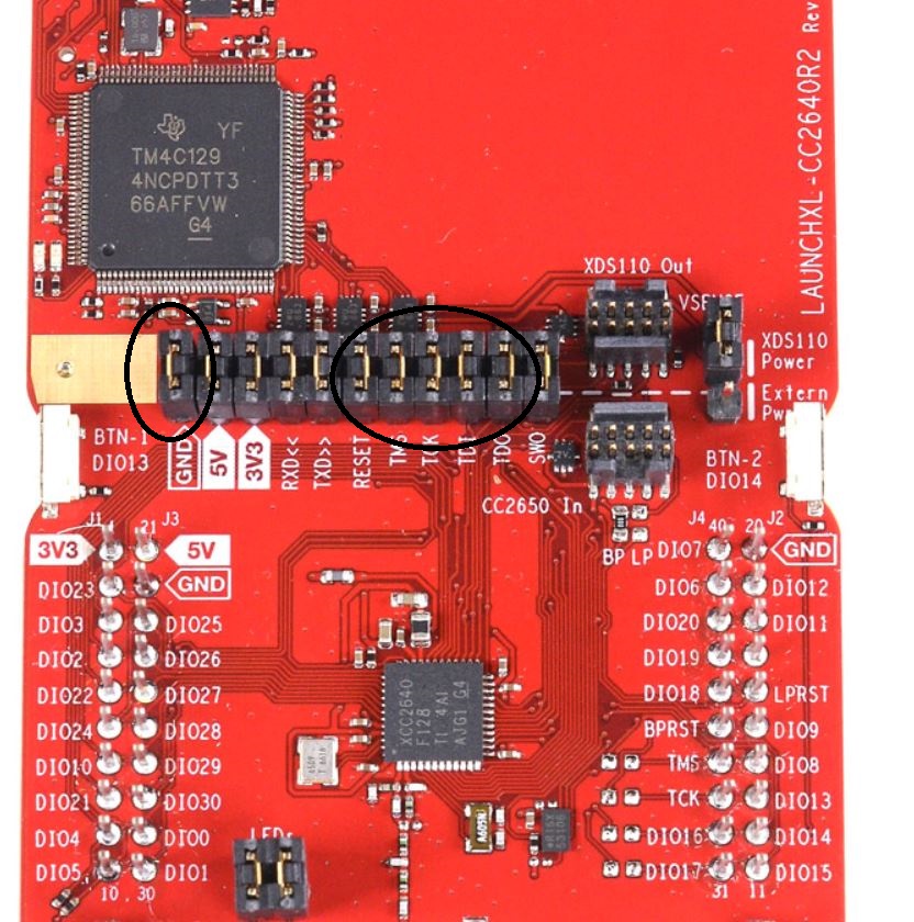
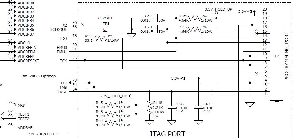
I have the micro pins TRST connected to the RESET line

TDO - TDO

TDI - TDI

TMS - TMS

TCK - TCK

GND - GND

Are there additional lines I need to be connecting to the micro?  Why would I be getting this error?  I'm stuck at this point and not sure how to move forward.

  • HI,

    Can you send a photograph of your setup, showing which pins of the launchpad are connecting to which pins of the F2808 header? That would help isolate the root cause. 

    Regards,

    Rafael

  • The jumpers circled in black were removed, and I connected my jumper wires from the top side to my board under test.

  • Hi,

    Thanks for sending the photos. Two considerations:

    - The C2000 designs usually have a strong pull down on the nTRST signal - the 2.21kΩ resistor. I would increase that to at least 4.7kΩ

    Reference: section Invalid data read back of the Debugging JTAG page at:

    https://software-dl.ti.com/ccs/esd/documents/ccs_debugging_jtag_connectivity_issues.html 

    - The pull ups on TDI, TMS and TCK should not be needed.

    Reference: section Target Connection Design of the XDS Target Connection Guide page at:

    https://software-dl.ti.com/ccs/esd/documents/xdsdebugprobes/emu_xds_target_connection_guide.html 

    - TDI and TDO should be connected to the pins of the same name on the target device. 

    Reference: same as above. 

    I will think of additional details and report back in case I can think of any relevant tips.

    Regards,

    Rafael

  • I know the end user of this board doesn't have issues connecting with it, so I am hesitant to say a board change is needed.  I could see a difference in drive strength between the programmer I am using the portentially the one they are using... so I will check these tomorrow and see.

    Otherwise I'm wondering if there is an issue in the IDE, JTAG clock speed, etc.  I could not find where to change the clock speed in the IDE, but I'm thinking that would be a good test too.

  • I changed the pulldown on the TRST line to 10K, it didn't make any difference.

  •  This is the nTRST line at the micro.  The noise I'm sure is a result of the cabling.  The voltage rises to 2.4ishV

  • Hi,

    Brandon Magnan said:
    I know the end user of this board doesn't have issues connecting with it, so I am hesitant to say a board change is needed.  I could see a difference in drive strength between the programmer I am using the portentially the one they are using... so I will check these tomorrow and see.

    Yes, that is what I imagined. However, increasing the pulldown to 10kΩ should have helped with the connection. 

    The scoped output seems to be quite noisy. Perhaps you are experiencing ground loops or connections that are too long? Also, the 2.4V does not do any favours to the integrity. I would focus my attention to reduce that noise. Unfortunately it is difficult to pinpoint an exact root cause from here. 

    Brandon Magnan said:
    Otherwise I'm wondering if there is an issue in the IDE, JTAG clock speed, etc.  I could not find where to change the clock speed in the IDE, but I'm thinking that would be a good test too.

    You can try to follow the guidelines at the sticky post below. That could be a good and simple attempt. 

    https://e2e.ti.com/support/tools/ccs/f/81/t/821584 

    Hope this helps,

    Rafael

  • The noise was cleaned up with better probing on my end.  The signal looks nice, but no change.

    Any other thoughts?

  • Hi,

    Sorry about the delay; I got access to my boards and was able to test the XDS110 Debug Probe in both the LAUNCHXL-CC2640R2 and the standalone TMDSEMU110-U. What I found was that the standalone properly asserts the nTRST pin before trying to connect, which is a requirement of the F28x family of devices. The RESET signal on the launchpad did not perform this, thus causing the JTAG state machine to be in an unknown state. 

    LAUNCHXL-CC2640R2 (never triggers)

    TMDSEMU110-U (triggers at the initial nTRST assert)

    From that standpoint and the fact the nTRST signal is not routed out of the launchpad's built in XDS110, I have to assume the launchpad is not compatible with 5 wire JTAG used by the F28x family of devices. I also could not find a way to manually assert this signal, not from CCS nor using the xds110reset utility. 

    I will check additional details and report back to this thread if I find anything relevant. 

    Regards,

    Rafael

  • Ok, that's all I needed to hear.

    I am ordering another programmer.

    We can consider this topic closed.