Other Parts Discussed in Thread: LM35,
Tool/software: Code Composer Studio
Hi,
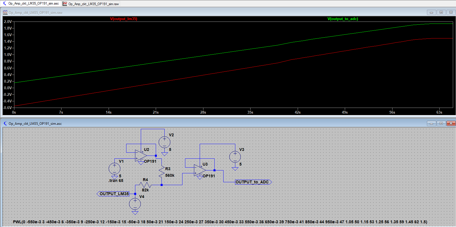
I have attached the LM35 DZ with cc3200 Launchpad as well as my custom board. I am giving the supply to sensor 5.14V. After that, I have the voltage divider circuit to reduce the voltage from 5v to 1.4v of sensor for ADC pin of cc3200 because cc3200 ADC pin voltage is 1.45. But, when the environmental temperature is varying, i can not any see any major changes in my sensor. Can I know why, what am I doing wrong?
I have taken the reference from ADC note and ADC demo also. But, i did not get any result. Please check the code for this and please tell me the alternative steps to find out the solution.
// Standard includes
#include <string.h>
#include <stdint.h>
#include <stdlib.h>
#include <stdbool.h>

// Driverlib includes
#include "utils.h"
#include "hw_memmap.h"
#include "hw_common_reg.h"
#include "hw_types.h"
#include "hw_adc.h"
#include "hw_ints.h"
#include "hw_gprcm.h"
#include "rom.h"
#include "rom_map.h"
#include "interrupt.h"
#include "prcm.h"
#include "uart.h"
#include "pinmux.h"
#include "pin.h"
#include "adc.h"

#include "adc_userinput.h"
#include "uart_if.h"

#define USER_INPUT
#define UART_PRINT         Report
#define FOREVER            1
#define APP_NAME           "ADC Reference"
#define NO_OF_SAMPLES 		128
#define MAXTIMINGS	85
unsigned long pulAdcSamples[4096];
int dht11_dat[5] = { 0, 0, 0, 0, 0 };
//*****************************************************************************
//                      GLOBAL VARIABLES
//*****************************************************************************
#if defined(ccs)
extern void (* const g_pfnVectors[])(void);
#endif
#if defined(ewarm)
extern uVectorEntry __vector_table;
#endif

/****************************************************************************/
/*                      LOCAL FUNCTION PROTOTYPES                           */
/****************************************************************************/
static void BoardInit(void);
static void DisplayBanner(char * AppName);

//*****************************************************************************
//
//! Application startup display on UART
//!
//! \param  none
//!
//! \return none
//!
//*****************************************************************************
static void
DisplayBanner(char * AppName)
{
    Report("\n\n\n\r");
    Report("\t\t *************************************************\n\r");
    Report("\t\t       CC3200 %s Application       \n\r", AppName);
    Report("\t\t *************************************************\n\r");
    Report("\n\n\n\r");
}

//*****************************************************************************
//
//! Board Initialization & Configuration
//!
//! \param  None
//!
//! \return None
//
//*****************************************************************************
static void
BoardInit(void)
{
/* In case of TI-RTOS vector table is initialize by OS itself */
#ifndef USE_TIRTOS
    //
    // Set vector table base
    //
#if defined(ccs)
    MAP_IntVTableBaseSet((unsigned long)&g_pfnVectors[0]);
#endif
#if defined(ewarm)
    MAP_IntVTableBaseSet((unsigned long)&__vector_table);
#endif
#endif
    //
    // Enable Processor
    //
    MAP_IntMasterEnable();
    MAP_IntEnable(FAULT_SYSTICK);

    PRCMCC3200MCUInit();
}

static void delay(unsigned int d)
{
    unsigned int i;
    for (i=0;i<d*100;i++){}
}

//*****************************************************************************
//
//! main - calls Crypt function after populating either from pre- defined vector
//! or from User
//!
//! \param  none
//!
//! \return none
//!
//*****************************************************************************
void
main()
{
    unsigned long  uiAdcInputPin;
    unsigned int  uiChannel;
    unsigned int  uiIndex=0;
    unsigned long ulSample;

    //
    // Initialize Board configurations
    //
    BoardInit();

    //
    // Configuring UART for Receiving input and displaying output
    // 1. PinMux setting
    // 2. Initialize UART
    // 3. Displaying Banner
    //
    PinMuxConfig();
    InitTerm();
    DisplayBanner(APP_NAME);

    while(FOREVER)
    {
        //
        // Initialize Array index for multiple execution
        //
        uiIndex=0;

        //
        // Read inputs from user
        //
//        if(!ReadFromUser(&uiAdcInputPin))
//        {
//          UART_PRINT("\n\rInvalid Input. Please try again. \n\r");
//          continue;
//        }

#ifdef CC3200_ES_1_2_1
        //
        // Enable ADC clocks.###IMPORTANT###Need to be removed for PG 1.32
        //
        HWREG(GPRCM_BASE + GPRCM_O_ADC_CLK_CONFIG) = 0x00000043;
        HWREG(ADC_BASE + ADC_O_ADC_CTRL) = 0x00000004;
        HWREG(ADC_BASE + ADC_O_ADC_SPARE0) = 0x00000100;
        HWREG(ADC_BASE + ADC_O_ADC_SPARE1) = 0x0355AA00;
#endif

        uiAdcInputPin= PIN_60;
        //
        // Pinmux for the selected ADC input pin
        //
        MAP_PinTypeADC(uiAdcInputPin,PIN_MODE_255);

        //
        // Convert pin number to channel number
        //
        switch(uiAdcInputPin)
        {
            case PIN_58:
                uiChannel = ADC_CH_1;
                break;
            case PIN_59:
                uiChannel = ADC_CH_2;
                break;
            case PIN_60:
                uiChannel = ADC_CH_3;
                break;
            default:
                break;
        }

        //
        // Configure ADC timer which is used to timestamp the ADC data samples
        //
        MAP_ADCTimerConfig(ADC_BASE,2^17);

        //
        // Enable ADC timer which is used to timestamp the ADC data samples
        //
        MAP_ADCTimerEnable(ADC_BASE);

        //
        // Enable ADC module
        //
        MAP_ADCEnable(ADC_BASE);

        //
        // Enable ADC channel
        //

        MAP_ADCChannelEnable(ADC_BASE, uiChannel);
        float samplesAveraged;
        while(uiIndex <10)
        {
            if(MAP_ADCFIFOLvlGet(ADC_BASE, uiChannel))
            {
                ulSample = MAP_ADCFIFORead(ADC_BASE, uiChannel);
                ulSample = (ulSample & 0x3ffc)>>2; //get bits [13:2]
                           //pulAdcSamples[uiIndex++] = ulSample;
                           samplesAveraged += (float)ulSample; //sum up all of the reading
                           uiIndex++;
            }
        }

        MAP_ADCChannelDisable(ADC_BASE, uiChannel);

        uiIndex = 0;

        //UART_PRINT("\n\rTotal no of 32 bit ADC data printed :4096 \n\r");
        //UART_PRINT("\n\rADC data format:\n\r");
        //UART_PRINT("\n\rbits[13:2] : ADC sample\n\r");
        //UART_PRINT("\n\rbits[31:14]: Time stamp of ADC sample \n\r");

        //
        // Print out ADC samples
        //

//        while(uiIndex < NO_OF_SAMPLES)
//        {
//            UART_PRINT("\n\rVoltage is %f\n\r",(((float)((pulAdcSamples[4+uiIndex] >> 2 ) & 0x0FFF))*1.4)/4096);
//            uiIndex++;
//        }
        float voltageResult;
        samplesAveraged = ( samplesAveraged/ 10.0f ); //get average
        voltageResult =  (float)(( (1.4f/ 4096.0f ) * samplesAveraged) ); //calculate mV
        UART_PRINT("\n\r voltage = %f",voltageResult);
        float temperature;
       // UART_PRINT("\n\rVoltage is %f\n\r",((float)((pulAdcSamples[4] >> 2 ) & 0x0FFF)*1.457)/4096);
       // output_voltage=((float)((pulAdcSamples[4] >> 2 ) & 0x0FFF)*1.457)/4096;
        temperature=((voltageResult)*100);
        UART_PRINT("\n\r temperature = %f",temperature);
        UART_PRINT("\n\r");
        delay(90000);


    }
}