This thread has been locked.

If you have a related question, please click the "Ask a related question" button in the top right corner. The newly created question will be automatically linked to this question.

CCS/TM4C1294NCPDT: CCS/TM4C1294

Part Number: TM4C1294NCPDT
Other Parts Discussed in Thread: LMX2594, MSP430F5529

Tool/software: Code Composer Studio

Hey, 

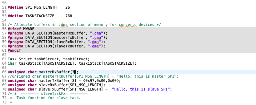
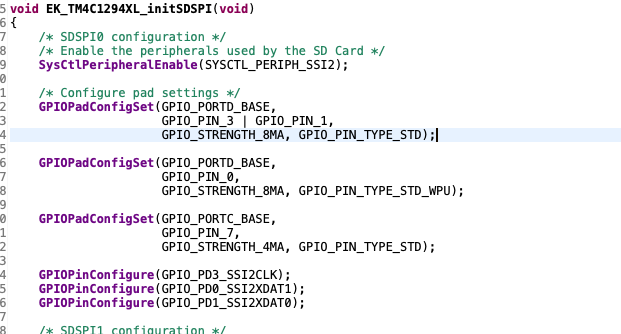
I am using the spiloopback example code using TM4C1294 evaluation kit. I am connecting TM4C to LMX2594. The wire connections are made proper. 

I am using the Port D for SPI and I am able to see the MOSI data in oscilloscope. But the MISO lines is always zero.

It would be great if you help through this. 

Thanks and regards, 

Srinivasan

  • Hello Srinivasan,

    There is not a lot of information here to work with. For starters, can you post the SSI configuration code so we can understand the settings you are using?

    Also it would be helpful to see the code for the data RX.

    Have you verified the clock speed and the SPI Mode are set correctly compared to the LMX2594 datasheet?

  • Hey Ralph, 

    Thanks for the reply. 

    1. I am using SSI2 configuration as given in the example code. I didn't make any changes. I am attaching ssi pin config data

    2. And LMX2594 can support upto 50MHz in SPI so that is not an issue. 

    Here is the complete explanation for my CCS project. 

    1. In Master Tx data I am  using character array with size 3{0x97,0x00,0x00}. I am trying to send this data through the inbuilt SPI transfer function. I am able to check the clock, chip select and Master output data through oscilloscope. But I am not able to see any data from the master input line. As soon as send my data through SPI  the LMX should send back the read back value to TM4C. But the MISO line is always zero and I am not receiving anything in TM4C. 

    2. And I am trying to program drive strength to 8mA through GPIOPADConfig but when running the program it still shows 2mA.

    Thanks and Regards, 

    Srinivasan

  • Hello Srinivasan,

    Likely the reason the drive strength is at 2mA is because this is called in the GPIOPinTypeSSI API.

    GPIOPadConfigSet(ui32Port, ui8Pins, GPIO_STRENGTH_2MA, GPIO_PIN_TYPE_STD);

    Which pin on the LMX2594 is the MISO line attached to? MUXout?

    I do not see the configuration for the SPI mode in the code attached - what is the SPI mode setting (SPI modes are numbers 0 through 3)?

  • Hey Ralph, 

    1. Yes the MISO line is connected to MUXout in LMX2594. 

    Yes I am using SSI2 from Port D, PD0,PD1,PD2,PD3.

    Also for drive strength I am changing GPIO_STRENGTH_2MA to GPIO_STRENGTH_8MA. In this case the drive strength should change and the register GPIODR8R should be set to 1 but it is always 0.

    Regards, 

    Srinivasan

  • Hello Srinivasan,

    Okay so looking through the TI-RTOS examples I see why my question about the SPI Mode setting is a bit confusing, they aren't clearly setting the SPI mode as I would expect.

    Digging through the source, it looks like it is being set to Mode 0, so that is correct based on the timing diagram for the LMX2594.

    So you are able to see the data output from the TM4C to the LMX2594 correctly then? And the LMX2594 is not responding to the command?

  • Hey Ralph, 

    Yes I couldn't  understand the SPI mode are you are asking about the QSSI or Legacy mode ? I am using Legacy mode. 

    And yes I am able see the data from Master output, but the Master input is always zero.

    Regards,

    Srinivasan

  • Hello Srinivasan,

    No there are four SPI modes based on clock phase and polarity: https://www.allaboutcircuits.com/technical-articles/spi-serial-peripheral-interface/

    I am going to see if someone familiar with the LMX2594 can comment here as I am not familiar with it at all, and from my POV the TM4C should be behaving correctly. Maybe they can help guide further here.

  • Hey Ralph, 

    Thanks for the reply. It would be good if someone could guide me in that. 

    I have one more query. I have also tried using MSP430F5529 Evaluation board as a slave and TM4C1294 Evaluation board as master(with the same spi ports and config). 

    I used that MSP430F55xx_usci_spi_standard_slave code. The code waits for master to send data and once the interrupt is received it takes the received data and sends back to the master. Even in that case MSP430F5529 didn't receive any interrupt but we could see Master out data in oscilloscope.

    Can you please check this issue to ? 

    Thanks and regards, 

    Srinivasan

  • Hi all,

    The MUXout of LMX2594 is not a MISO output. MUXout is either HIGH or LOW, but never hi-Z. So don't connect this pin to the MISO bus if the bus is connected to more than one devices. 

    MUXout is either a lock detect output or register read back data output. 

  • Hey, 

    Thanks for the reply, 

    Actually I am trying to read back the lock detect from LMX2594 from TM4C1294 EVAL Board. But it always shows the value zero. 

    Even I tried to do read back for the registers(R23) which has default non-zero value, even that I am getting as zero.

    Regards, 

    Srinivasan

  • Hello Noel,

    What is the typical way an MCU would read this information out? I may be able to guide Srinivasan on how to do so with TM4C, but I don't really understand which peripheral to suggest using here.

  • Hey Ralph and Noel, 

    Any updated on the LMX2594 MuXout read back from TM4C ?

  • Hi Ralph,

    I don't know how customers do it, they don't seem to have problem reading back the written register.

    One clarification, I was trying to say don't connect MUXout to the MOSI bus directly, but  we can still connect it to MOSI via a diode.