Part Number: LAUNCHXL-F28027F
Other Parts Discussed in Thread: TMS320F28027F, CONTROLSUITE
Tool/software: Code Composer Studio
I'm new with CCS v5. I have C2000 LaunchPadXL TMS320F28027F and I want to use it for BLDC Drive. I created new project and got "../main.c", line 2: fatal error #1965: cannot open source file "common/include/adc.h" this error. I tried to paths and libs but nothing of them worked. Also I opened example projects, tried to build but same errors were occured again. I'm making graduation project and stuck here, please help me.
You can find my main.c, screenshots of properties, and error below.
#include "DSP28x_Project.h"
#include "common/include/adc.h"
#include "common/include/clk.h"
#include "common/include/flash.h"
#include "common/include/gpio.h"
#include "common/include/pie.h"
#include "common/include/pll.h"
#include "common/include/timer.h"
#include "common/include/wdog.h"
#include "common/include/pwr.h"
#include "common/include/pwm.h"
#include "math.h"
#define INTPOOLCOUNT 50
#define INTEGRALCOUNTPERIOD 50000
__interrupt void adc_isr(void);
interrupt void cpu_timer0_isr(void);
interrupt void cpu_timer1_isr(void);
__interrupt void xint1_isr(void);
__interrupt void xint2_isr(void);
__interrupt void xint3_isr(void);
void pwm_Init_();
void pwm2_Init_();
void pwm3_Init_();
void gpio_init();
void adc_init();
void delay_loop(void);
unsigned int period = 5000;
unsigned int halfperiod;
unsigned int CMPA;
int DEADTIME=2; //MIKROSANIYE HIGHLAR VE LOWLAR ARASI BEKLEME
int initial=0;
int desired=0;
int i=0,j=0;
int gas_value=200;
int gastest=0;
int GAS_POOL[10]={0,0,0,0,0,0,0,0,0,0};
int INTEGRAL_POOL[INTPOOLCOUNT];
int integralpoolcounter=0;
float INTEGRAL;
float DERIVATIVE;
float PROPORTIONAL;
//
float KINTEGRAL;
float KDERIVATIVE;
float KPROPORTIONAL;
//
int pidoutput;
int hallbinary,hall1,hall2,hall3;
int deadman=0;
int counter1 = 0;
int counter2 = 0;
int counter3 = 0;
int counter_adc=0;
long int temp=0,inttemp=0;
int rpm;
int error,lasterror;
int counterdd=0;
int start=0;
int adc2=0;
int timer2count=0;
int timer1count=0;
int can=0;
int timerstart=0;
int close_signal=0;
ADC_Handle myAdc;
CLK_Handle myClk;
FLASH_Handle myFlash;
GPIO_Handle myGpio;
PIE_Handle myPie;
PLL_Handle myPll;
TIMER_Handle myTimer;
TIMER_Handle myTimer1;
WDOG_Handle myWDog;
PWR_Handle MyPwr;
CPU_Handle myCpu;
PWM_Handle myPwm1;
PWM_Handle myPwm2;
PWM_Handle myPwm3;
PWM_Handle adcepwm;
int main(void){
myAdc = ADC_init((void *)ADC_BASE_ADDR, sizeof(ADC_Obj));
myClk = CLK_init((void *)CLK_BASE_ADDR, sizeof(CLK_Obj));
myFlash = FLASH_init((void *)FLASH_BASE_ADDR, sizeof(FLASH_Obj));
myGpio = GPIO_init((void *)GPIO_BASE_ADDR, sizeof(GPIO_Obj));
myPie = PIE_init((void *)PIE_BASE_ADDR, sizeof(PIE_Obj));
myPll = PLL_init((void *)PLL_BASE_ADDR, sizeof(PLL_Obj));
myTimer = TIMER_init((void *)TIMER0_BASE_ADDR, sizeof(TIMER_Obj));
myTimer1 = TIMER_init((void *)TIMER1_BASE_ADDR, sizeof(TIMER_Obj));
myWDog = WDOG_init((void *)WDOG_BASE_ADDR, sizeof(WDOG_Obj));
myCpu = CPU_init((void *)NULL, sizeof(CPU_Obj));
myPwm1 = PWM_init((void *)PWM_ePWM2_BASE_ADDR, sizeof(PWM_Obj));
myPwm2 = PWM_init((void *)PWM_ePWM3_BASE_ADDR, sizeof(PWM_Obj));
myPwm3 = PWM_init((void *)PWM_ePWM1_BASE_ADDR, sizeof(PWM_Obj));
adcepwm = PWM_init((void *)PWM_ePWM4_BASE_ADDR, sizeof(PWM_Obj));
WDOG_disable(myWDog);
CLK_enableAdcClock(myClk);
(*Device_cal)();
CLK_setOscSrc(myClk, CLK_OscSrc_Internal);
PLL_setup(myPll, PLL_Multiplier_10, PLL_DivideSelect_ClkIn_by_2);
PIE_disable(myPie);
PIE_disableAllInts(myPie);
CPU_disableGlobalInts(myCpu);
CPU_clearIntFlags(myCpu);
#ifdef _FLASH
memcpy(&RamfuncsRunStart, &RamfuncsLoadStart, (size_t)&RamfuncsLoadSize);
#endif
PIE_setDebugIntVectorTable(myPie);
PIE_enable(myPie);
PIE_registerPieIntHandler(myPie, PIE_GroupNumber_1, PIE_SubGroupNumber_4,(intVec_t)&xint1_isr);
PIE_registerPieIntHandler(myPie, PIE_GroupNumber_1, PIE_SubGroupNumber_5,(intVec_t)&xint2_isr);
PIE_registerPieIntHandler(myPie, PIE_GroupNumber_12, PIE_SubGroupNumber_1, (intVec_t)&xint3_isr);
//PIE_registerPieIntHandler(myPie, PIE_GroupNumber_1, PIE_SubGroupNumber_7, (intVec_t)&cpu_timer0_isr);
PIE_registerPieIntHandler(myPie, PIE_GroupNumber_10, PIE_SubGroupNumber_1, (intVec_t)&adc_isr);
//PIE_registerSystemIntHandler(myPie, PIE_SystemInterrupts_TINT1, (intVec_t)&cpu_timer1_isr);
ADC_enableBandGap(myAdc);
ADC_enableRefBuffers(myAdc);
ADC_powerUp(myAdc);
ADC_enable(myAdc);
ADC_setVoltRefSrc(myAdc, ADC_VoltageRefSrc_Int);
/*TIMER_stop(myTimer);
TIMER_setPeriod(myTimer,5000000000);
TIMER_setPreScaler(myTimer, 0);
TIMER_reload(myTimer);
TIMER_setEmulationMode(myTimer, TIMER_EmulationMode_StopAfterNextDecrement);
TIMER_enableInt(myTimer);
TIMER_start(myTimer);*/
//TIMER0 ILE EXTERNAL INTERRUPTLAR AYNI ANDA CALISMAZ
TIMER_stop(myTimer1);
TIMER_setPeriod(myTimer1, 50000);
TIMER_setPreScaler(myTimer1, 0);
TIMER_reload(myTimer1);
TIMER_setEmulationMode(myTimer1, TIMER_EmulationMode_StopAfterNextDecrement);
TIMER_enableInt(myTimer1);
TIMER_start(myTimer1);
PIE_enableInt(myPie, PIE_GroupNumber_1, PIE_InterruptSource_XINT_1);
PIE_enableInt(myPie, PIE_GroupNumber_1, PIE_InterruptSource_XINT_2);
PIE_enableInt(myPie, PIE_GroupNumber_12, PIE_InterruptSource_XINT_3);
CPU_enableInt(myCpu, CPU_IntNumber_1);//XINT1,XINT2
CPU_enableInt(myCpu, CPU_IntNumber_12);//XINT3
//CPU_enableInt(myCpu, CPU_IntNumber_13);//TIMER1 INTERRUPT REGISTER
CPU_enableInt(myCpu, CPU_IntNumber_10);//ADC INTERRUPT REGISTER
//PIE_enableTimer0Int(myPie);
PIE_enableAdcInt(myPie, ADC_IntNumber_1);
CPU_enableGlobalInts(myCpu);
CPU_enableDebugInt(myCpu);
ADC_setIntPulseGenMode(myAdc, ADC_IntPulseGenMode_Prior);
ADC_enableInt(myAdc, ADC_IntNumber_1);
ADC_setIntMode(myAdc, ADC_IntNumber_1, ADC_IntMode_ClearFlag);
ADC_setIntSrc(myAdc, ADC_IntNumber_1, ADC_IntSrc_EOC2);
ADC_setSocChanNumber (myAdc, ADC_SocNumber_1, ADC_SocChanNumber_A6);
ADC_setSocTrigSrc(myAdc, ADC_SocNumber_1, ADC_SocTrigSrc_EPWM4_ADCSOCA);
ADC_setSocSampleWindow(myAdc, ADC_SocNumber_1, ADC_SocSampleWindow_14_cycles);//CALISMAZSA 7 CYCLE YAP
//ADC PWM
CLK_enablePwmClock(myClk, PWM_Number_4);
PWM_enableSocAPulse(adcepwm); // SOC ACILIMI
PWM_setSocAPulseSrc(adcepwm, PWM_SocPulseSrc_CounterEqualCmpAIncr);
PWM_setSocAPeriod(adcepwm, PWM_SocPeriod_FirstEvent);
PWM_setCmpA(adcepwm, 0x0080); //CMPA DEGERI
PWM_setPeriod(adcepwm, 0xFFFF); //1ms
PWM_setCounterMode(adcepwm, PWM_CounterMode_Up); // count up and start
//ADC PWM BITIS
gpio_init();
PIE_setExtIntPolarity(myPie, CPU_ExtIntNumber_1, PIE_ExtIntPolarity_RisingAndFallingEdge);
PIE_setExtIntPolarity(myPie, CPU_ExtIntNumber_2, PIE_ExtIntPolarity_RisingAndFallingEdge);
PIE_setExtIntPolarity(myPie, CPU_ExtIntNumber_3, PIE_ExtIntPolarity_RisingAndFallingEdge);
PIE_enableExtInt(myPie, CPU_ExtIntNumber_1);
PIE_enableExtInt(myPie, CPU_ExtIntNumber_2);
PIE_enableExtInt(myPie, CPU_ExtIntNumber_3);
CLK_disableTbClockSync(myClk);
pwm_Init_();
pwm2_Init_();
pwm3_Init_();
CLK_enableTbClockSync(myClk);
//MOTOR ILK ACILDIGINDA INTERRUPT OLMAYACAGINDAN ILK HALL DURUMLARINI ALMAMIZ GEREKIR
hall1 = GPIO_getData(myGpio, GPIO_Number_19);
hall2 = GPIO_getData(myGpio, GPIO_Number_28);
hall3 = GPIO_getData(myGpio, GPIO_Number_29);
hallbinary=hall1+(hall2<<1)+(hall3<<2);
while(1){
gas_value=ADC_readResult(myAdc, ADC_ResultNumber_1);
if(gas_value<200){
start=0;
}
if(gas_value<400){
gas_value=0;
}
if(gas_value>=400){
start=1;
}
CMPA = ((float)gas_value / 4095.0) * (float)period;
//deadman=GPIO_getData(myGpio, GPIO_Number_34);
deadman=0;
if(deadman==1){
CMPA=0;
}
if(start==0){
//START-STOP KISMINDA KAPASITE DOLUMLARI HALL SENSORLERE ETKI ETMEDEN
GPIO_setLow(myGpio, GPIO_Number_4);
GPIO_setLow(myGpio, GPIO_Number_0);
GPIO_setHigh(myGpio, GPIO_Number_2);
delay_loop();
GPIO_setLow(myGpio, GPIO_Number_4);
GPIO_setHigh(myGpio, GPIO_Number_0);
GPIO_setLow(myGpio, GPIO_Number_2);
delay_loop();
GPIO_setHigh(myGpio, GPIO_Number_4);
GPIO_setLow(myGpio, GPIO_Number_0);
GPIO_setLow(myGpio, GPIO_Number_2);
delay_loop();
GPIO_setLow(myGpio, GPIO_Number_4);
GPIO_setLow(myGpio, GPIO_Number_0);
GPIO_setLow(myGpio, GPIO_Number_2);
delay_loop();
}
/*hall1 = GPIO_getData(myGpio, GPIO_Number_19);
hall2 = GPIO_getData(myGpio, GPIO_Number_28);
hall3 = GPIO_getData(myGpio, GPIO_Number_29);
*/
hallbinary=hall1+(hall2<<1)+(hall3<<2);
switch(hallbinary)
{
case 5:
PWM_setCmpA(myPwm1, 0); //faz1 HIGH
PWM_setCmpA(myPwm2, CMPA); //faz2 HIGH
PWM_setCmpA(myPwm3, 0); //faz3 HIGH
DELAY_US(10);
GPIO_setLow(myGpio, GPIO_Number_4); //faz1 LOW
GPIO_setLow(myGpio, GPIO_Number_0); //faz2 LOW
GPIO_setHigh(myGpio, GPIO_Number_2); //faz3 LOW
break;
case 2:
PWM_setCmpA(myPwm1, 0);
PWM_setCmpA(myPwm2, 0);
PWM_setCmpA(myPwm3, CMPA);
DELAY_US(10);
GPIO_setLow(myGpio, GPIO_Number_4);
GPIO_setHigh(myGpio, GPIO_Number_0);
GPIO_setLow(myGpio, GPIO_Number_2);
break;
case 3:
PWM_setCmpA(myPwm1, 0);
PWM_setCmpA(myPwm2, 0);
PWM_setCmpA(myPwm3, CMPA);
DELAY_US(10);
GPIO_setHigh(myGpio, GPIO_Number_4);
GPIO_setLow(myGpio, GPIO_Number_0);
GPIO_setLow(myGpio, GPIO_Number_2);
break;
case 4:
PWM_setCmpA(myPwm1, CMPA);
PWM_setCmpA(myPwm2, 0);
PWM_setCmpA(myPwm3, 0);
DELAY_US(10);
GPIO_setLow(myGpio, GPIO_Number_4);
GPIO_setLow(myGpio, GPIO_Number_0);
GPIO_setHigh(myGpio, GPIO_Number_2);
break;
case 6:
PWM_setCmpA(myPwm1, CMPA);
PWM_setCmpA(myPwm2, 0);
PWM_setCmpA(myPwm3, 0);
DELAY_US(10);
GPIO_setLow(myGpio, GPIO_Number_4);
GPIO_setHigh(myGpio, GPIO_Number_0);
GPIO_setLow(myGpio, GPIO_Number_2);
break;
case 1:
PWM_setCmpA(myPwm1, 0);
PWM_setCmpA(myPwm2, CMPA);
PWM_setCmpA(myPwm3, 0);
DELAY_US(10);
GPIO_setHigh(myGpio, GPIO_Number_4);
GPIO_setLow(myGpio, GPIO_Number_0);
GPIO_setLow(myGpio, GPIO_Number_2);
break;
default:
PWM_setCmpA(myPwm1, 0);
PWM_setCmpA(myPwm2, 0);
PWM_setCmpA(myPwm3, 0);
DELAY_US(10);
GPIO_setLow(myGpio, GPIO_Number_4);
GPIO_setLow(myGpio, GPIO_Number_0);
GPIO_setLow(myGpio, GPIO_Number_2);
}
}
}
//-------------------------- Interrupts -----------------------------------
__interrupt void adc_isr(void){
GAS_POOL[counter_adc]=ADC_readResult(myAdc, ADC_ResultNumber_1);
if(counter_adc==9)counter_adc=0;
counter_adc++;
for(i=0;i<9;i++){
temp+=GAS_POOL[i];
}
gastest=temp/10;
ADC_clearIntFlag(myAdc, ADC_IntNumber_1);
PIE_clearInt(myPie, PIE_GroupNumber_10);
}
interrupt void cpu_timer1_isr(void){
/*
rpm=(int)(416666.66/(float)halfperiod);
error=desired-rpm;
//INTEGRAL
INTEGRAL_POOL[integralpoolcounter]=error;
integralpoolcounter++;
if(integralpoolcounter==INTPOOLCOUNT)integralpoolcounter=0;
for(j=0;j<INTPOOLCOUNT;j++){
inttemp+=INTEGRAL_POOL[j];
}
INTEGRAL=KINTEGRAL*inttemp;
//DERIVATIVE
DERIVATIVE=KDERIVATIVE*(error-lasterror/INTEGRALCOUNTPERIOD);
lasterror=error;
//PROPORTIONAL
PROPORTIONAL = error*KPROPORTIONAL;
//END
pidoutput=INTEGRAL+PROPORTIONAL+DERIVATIVE;*/
}
__interrupt void xint1_isr(void){//INTERRUPTLARDA HALL KACIRMAMAK ICIN HEPSINE BAKIYORUZ 1. HALLDEN HIZ OKUMASI ALIYORUZ
/*if(timerstart){
halfperiod=0;
TIMER_reload(myTimer);
timerstart=0;
}else{
halfperiod=TIMER_getCount(myTimer);
timerstart=1;
}*/
hall1 = GPIO_getData(myGpio, GPIO_Number_19);
PIE_clearInt(myPie, PIE_GroupNumber_1);
}
__interrupt void xint2_isr(void){//INTERRUPTLARDA HALL KACIRMAMAK ICIN HEPSINE BAKIYORUZ
hall2 = GPIO_getData(myGpio, GPIO_Number_28);
PIE_clearInt(myPie, PIE_GroupNumber_1);
}
__interrupt void xint3_isr(void){//INTERRUPTLARDA HALL KACIRMAMAK ICIN HEPSINE BAKIYORUZ
hall3 = GPIO_getData(myGpio, GPIO_Number_29);
PIE_clearInt(myPie, PIE_GroupNumber_12);
}
//--------------------------------- PWM ------------------------------------
void pwm_Init_()
{
CLK_enablePwmClock(myClk, PWM_Number_2);
PWM_enableSocAPulse(myPwm1);
PWM_setSocAPulseSrc(myPwm1, PWM_SocPulseSrc_CounterEqualCmpAIncr);
PWM_setSocAPeriod(myPwm1, PWM_SocPeriod_FirstEvent);
PWM_setPeriod(myPwm1, period);
PWM_setCounterMode(myPwm1, PWM_CounterMode_Up);
PWM_disableCounterLoad(myPwm1);
PWM_setPhase(myPwm1, 0x0000);
PWM_setCount(myPwm1, 0x0000);
PWM_setHighSpeedClkDiv(myPwm1, PWM_HspClkDiv_by_1);
PWM_setClkDiv(myPwm1, PWM_ClkDiv_by_1);
PWM_setShadowMode_CmpA(myPwm1, PWM_ShadowMode_Shadow);
PWM_setLoadMode_CmpA(myPwm1, PWM_LoadMode_Zero);
PWM_setShadowMode_CmpB(myPwm1, PWM_ShadowMode_Shadow);
PWM_setLoadMode_CmpB(myPwm1, PWM_LoadMode_Zero);
PWM_setActionQual_Zero_PwmA(myPwm1, PWM_ActionQual_Set);
PWM_setActionQual_CntUp_CmpA_PwmA(myPwm1, PWM_ActionQual_Clear);
PWM_setActionQual_Zero_PwmB(myPwm1, PWM_ActionQual_Set);
PWM_setActionQual_CntUp_CmpA_PwmB(myPwm1, PWM_ActionQual_Clear);
PWM_setCmpA(myPwm1, 0);
//DEADBAND YAPMAMIZA GEREK YOK CUNKU BIZ IKI FARKLI PWM KAYNAGINDAN SURUS YAPMIYORUZ
//LOW SIDELARA DIREK 5V VERIYORUZ
//EGER PWM MODUL A VE B DEN AYRI AYRI SURSEYDIK GEREKIRDI
}
void pwm2_Init_()
{
CLK_enablePwmClock(myClk, PWM_Number_3);
PWM_enableSocAPulse(myPwm2);
PWM_setSocAPulseSrc(myPwm2, PWM_SocPulseSrc_CounterEqualCmpAIncr);
PWM_setSocAPeriod(myPwm2, PWM_SocPeriod_FirstEvent);
PWM_setPeriod(myPwm2, period);
PWM_setCounterMode(myPwm2, PWM_CounterMode_Up);
PWM_disableCounterLoad(myPwm2);
PWM_setPhase(myPwm2, 0x0000);
PWM_setCount(myPwm2, 0x0000);
PWM_setHighSpeedClkDiv(myPwm2, PWM_HspClkDiv_by_1);
PWM_setClkDiv(myPwm2, PWM_ClkDiv_by_1);
PWM_setShadowMode_CmpA(myPwm2, PWM_ShadowMode_Shadow);
PWM_setLoadMode_CmpA(myPwm2, PWM_LoadMode_Zero);
PWM_setShadowMode_CmpB(myPwm2, PWM_ShadowMode_Shadow);
PWM_setLoadMode_CmpB(myPwm2, PWM_LoadMode_Zero);
PWM_setActionQual_Zero_PwmA(myPwm2, PWM_ActionQual_Set);
PWM_setActionQual_CntUp_CmpA_PwmA(myPwm2, PWM_ActionQual_Clear);
PWM_setActionQual_Zero_PwmB(myPwm2, PWM_ActionQual_Set);
PWM_setActionQual_CntUp_CmpA_PwmB(myPwm2, PWM_ActionQual_Clear);
PWM_setCmpA(myPwm2, 0);
//DEADBAND YAPMAMIZA GEREK YOK CUNKU BIZ IKI FARKLI PWM KAYNAGINDAN SURUS YAPMIYORUZ
//LOW SIDELARA DIREK 5V VERIYORUZ
//EGER PWM MODUL A VE B DEN AYRI AYRI SURSEYDIK GEREKIRDI
}
void pwm3_Init_()
{
CLK_enablePwmClock(myClk, PWM_Number_1);
PWM_enableSocAPulse(myPwm3);
PWM_setSocAPulseSrc(myPwm3, PWM_SocPulseSrc_CounterEqualCmpAIncr);
PWM_setSocAPeriod(myPwm3, PWM_SocPeriod_FirstEvent);
PWM_setPeriod(myPwm3, period);
PWM_setCounterMode(myPwm3, PWM_CounterMode_Up);
PWM_disableCounterLoad(myPwm3);
PWM_setPhase(myPwm3, 0x0000);
PWM_setCount(myPwm3, 0x0000);
PWM_setHighSpeedClkDiv(myPwm3, PWM_HspClkDiv_by_1);
PWM_setClkDiv(myPwm3, PWM_ClkDiv_by_1);
PWM_setShadowMode_CmpA(myPwm3, PWM_ShadowMode_Shadow);
PWM_setLoadMode_CmpA(myPwm3, PWM_LoadMode_Zero);
PWM_setShadowMode_CmpB(myPwm3, PWM_ShadowMode_Shadow);
PWM_setLoadMode_CmpB(myPwm3, PWM_LoadMode_Zero);
PWM_setActionQual_Zero_PwmA(myPwm3, PWM_ActionQual_Set);
PWM_setActionQual_CntUp_CmpA_PwmA(myPwm3, PWM_ActionQual_Clear);
PWM_setActionQual_Zero_PwmB(myPwm3, PWM_ActionQual_Set);
PWM_setActionQual_CntUp_CmpA_PwmB(myPwm3, PWM_ActionQual_Clear);
PWM_setCmpA(myPwm3, 0);
//DEADBAND YAPMAMIZA GEREK YOK CUNKU BIZ IKI FARKLI PWM KAYNAGINDAN SURUS YAPMIYORUZ
//LOW SIDELARA DIREK 5V VERIYORUZ
//EGER PWM MODUL A VE B DEN AYRI AYRI SURSEYDIK GEREKIRDI
}
//-------------------------- Initials -----------------------------------
void gpio_init(){
GPIO_setMode(myGpio, GPIO_Number_19, GPIO_19_Mode_GeneralPurpose);
GPIO_setMode(myGpio, GPIO_Number_28, GPIO_28_Mode_GeneralPurpose);
GPIO_setMode(myGpio, GPIO_Number_29, GPIO_29_Mode_GeneralPurpose);
GPIO_setPullUp(myGpio, GPIO_Number_19, GPIO_PullUp_Enable);
GPIO_setPullUp(myGpio, GPIO_Number_28, GPIO_PullUp_Enable);
GPIO_setPullUp(myGpio, GPIO_Number_29, GPIO_PullUp_Enable);
GPIO_setDirection(myGpio, GPIO_Number_19, GPIO_Direction_Input);
GPIO_setDirection(myGpio, GPIO_Number_28, GPIO_Direction_Input);
GPIO_setDirection(myGpio, GPIO_Number_29, GPIO_Direction_Input);
/*GPIO_setQualification(myGpio, GPIO_Number_19, GPIO_Qual_ASync);
GPIO_setQualification(myGpio, GPIO_Number_28, GPIO_Qual_ASync);
GPIO_setQualification(myGpio, GPIO_Number_29, GPIO_Qual_ASync);
//INTERRUPTLAR GIRMEZSE ACABILIRSIN
GPIO_setQualificationPeriod(myGpio, GPIO_Number_28, 0xFF);*/
GPIO_setExtInt(myGpio, GPIO_Number_19, CPU_ExtIntNumber_1);
GPIO_setExtInt(myGpio, GPIO_Number_28, CPU_ExtIntNumber_2);
GPIO_setExtInt(myGpio, GPIO_Number_29, CPU_ExtIntNumber_3);
GPIO_setMode(myGpio, GPIO_Number_34, GPIO_34_Mode_GeneralPurpose);
GPIO_setDirection(myGpio, GPIO_Number_34, GPIO_Direction_Input);
GPIO_setPullUp(myGpio, GPIO_Number_34, GPIO_PullUp_Enable);
//high
GPIO_setMode(myGpio, GPIO_Number_3, GPIO_3_Mode_EPWM2B);
//low
GPIO_setMode(myGpio, GPIO_Number_4, GPIO_4_Mode_GeneralPurpose);
GPIO_setDirection(myGpio, GPIO_Number_4, GPIO_Direction_Output);
GPIO_setLow(myGpio, GPIO_Number_4);
//high
GPIO_setMode(myGpio, GPIO_Number_5, GPIO_5_Mode_EPWM3B);
//low
GPIO_setMode(myGpio, GPIO_Number_0, GPIO_0_Mode_GeneralPurpose);
GPIO_setDirection(myGpio, GPIO_Number_0, GPIO_Direction_Output);
GPIO_setLow(myGpio, GPIO_Number_0);
//high
GPIO_setMode(myGpio, GPIO_Number_1, GPIO_1_Mode_EPWM1B);
//low
GPIO_setMode(myGpio, GPIO_Number_2, GPIO_2_Mode_GeneralPurpose);
GPIO_setDirection(myGpio, GPIO_Number_2, GPIO_Direction_Output);
GPIO_setLow(myGpio, GPIO_Number_2);
GPIO_setPullUp(myGpio, GPIO_Number_0, GPIO_PullUp_Disable);
GPIO_setPullUp(myGpio, GPIO_Number_1, GPIO_PullUp_Disable);
GPIO_setPullUp(myGpio, GPIO_Number_2, GPIO_PullUp_Disable);
GPIO_setPullUp(myGpio, GPIO_Number_3, GPIO_PullUp_Disable);
GPIO_setPullUp(myGpio, GPIO_Number_4, GPIO_PullUp_Disable);
GPIO_setPullUp(myGpio, GPIO_Number_5, GPIO_PullUp_Disable);
}
void delay_loop()
{
short i,j;
for (j = 0; j < 1; j++) {
for (i = 0; i < 30000; i++) {
}
}
}
ERROR:
**** Build of configuration Debug for project bldc_driver ****
"C:\\ti\\ccsv5\\utils\\bin\\gmake" -k all
'Building file: ../main.c'
'Invoking: C2000 Compiler'
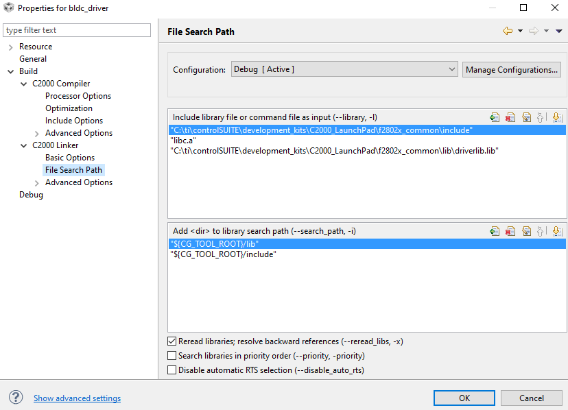
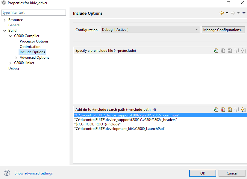
"C:/ti/ccsv5/tools/compiler/c2000_6.2.0/bin/cl2000" -v28 -ml -mt --include_path="C:/ti/controlSUITE/device_support/f2802x/v230/f2802x_common" --include_path="C:/ti/controlSUITE/device_support/f2802x/v230/f2802x_headers" --include_path="C:/ti/ccsv5/tools/compiler/c2000_6.2.0/include" --include_path="C:/ti/controlSUITE/development_kits/C2000_LaunchPad" -g --diag_warning=225 --display_error_number --diag_wrap=off --preproc_with_compile --preproc_dependency="main.pp" "../main.c"
"../main.c", line 2: fatal error #1965: cannot open source file "common/include/adc.h"
1 catastrophic error detected in the compilation of "../main.c".
Compilation terminated.
SCREENSHOTS OF PROPERTIES: