This thread has been locked.

If you have a related question, please click the "Ask a related question" button in the top right corner. The newly created question will be automatically linked to this question.

CCS/TMS320C6678: C6000 interrupts jitter

Part Number: TMS320C6678
Other Parts Discussed in Thread: SYSBIOS

Tool/software: Code Composer Studio

Hello, 

I'm using for my development a control board with a C2000 and a C6000 connected together. The trouble I have today is about a jitter I observed between the time the interruption should fire and the time it really fires. 

To explain a bit my configuration: 

The C2000 trigs the C6000 gpio via a supply translating transceiver, which is connected to GPIO12 on my C6000. In the C6000 code, there are currently 2 IT initialized, one for this GPIO, and one for a timer at 500µs. 

These are initialized as follow, for the Interrupt vector table: 

.ref _c_int00
	.ref OS_Tick
	.ref COMMCU_FastTrig
	.ref _nmi_isr
	.ref CANXCP_HandlerMCU
;------------------------------------------------------------------------------
; Fonctions
;------------------------------------------------------------------------------
	.sect "IntTbl"
	.align 1024

; Prevent assembler from using 16-bit compact instructions
    .nocmp

RESET_RST:
	    MVKL .S2 _c_int00, B0
	    MVKH .S2 _c_int00, B0
	    B    .S2 B0
		NOP
		NOP
		NOP
		NOP
	    NOP
NMI_RST:
	    MVKL .S2 _nmi_isr, B0
		MVKH .S2 _nmi_isr, B0
		B    .S2 B0
		NOP
		NOP
		NOP
		NOP
		NOP

RESV1:
	    NOP
		NOP
		NOP
		NOP
		NOP
		NOP
		NOP
		NOP

RESV2:
	    NOP
		NOP
		NOP
		NOP
		NOP
		NOP
		NOP
		NOP

INT4:
		NOP
		NOP
		NOP
		NOP
		NOP
		NOP
		NOP
		NOP

INT5:
		NOP
		NOP
		NOP
		NOP
		NOP
		NOP
		NOP
		NOP

INT6:
		NOP
		NOP
		NOP
		NOP
		NOP
		NOP
		NOP
		NOP

INT7:
		NOP
		NOP
		NOP
		NOP
		NOP
		NOP
		NOP
		NOP

INT8:
        NOP
        NOP
        NOP
        NOP
        NOP
        NOP
        NOP
        NOP

INT9:
		NOP
		NOP
		NOP
		NOP
		NOP
		NOP
		NOP
		NOP

INT10:
		NOP
		NOP
		NOP
		NOP
		NOP
		NOP
		NOP
		NOP

INT11:
		NOP
		NOP
		NOP
		NOP
		NOP
		NOP
		NOP
		NOP

INT12:
		NOP
		NOP
		NOP
		NOP
		NOP
		NOP
		NOP
		NOP

INT13:
        STW  .D2 B0,*b15--[2]           ; temp save b0 on stack
        MVKL .S2 COMMCU_FastTrig,B0     ; load destination address to b0
        MVKH .S2 COMMCU_FastTrig,B0
        B    .S2 B0                     ; start branch to destination
        LDW  .D2 *++b15[2],B0           ; restore b0 register
        NOP 2                           ; fill 2 of b0 restore delay slots
        NOP                             ; fill delay slot, pad packet
        NOP                             ; fill delay slot, pad packet

INT14:
		STW  .D2 B0,*b15--[2]   ; temp save b0 on stack
        MVKL .S2 OS_Tick,B0 	; load destination address to b0
        MVKH .S2 OS_Tick,B0
        B    .S2 B0             ; start branch to destination
        LDW  .D2 *++b15[2],B0   ; restore b0 register
        NOP 2                   ; fill 2 of b0 restore delay slots
        NOP                     ; fill delay slot, pad packet
        NOP                     ; fill delay slot, pad packet


INT15:
		NOP
		NOP
		NOP
		NOP
		NOP
		NOP
		NOP
		NOP

For the code itself: 

//! Event related to the timer0
#define INT_kEVT_TIMER0 (64)
//! Event related to GPIO12
#define INT_kEVT_GPIO12 (86)

extern far unsigned int ISTP_START;

#pragma DATA_SECTION(INT_stCorePacRegs,"IntCorePacRegsFile");
volatile struct INT_tstCorePacRegs INT_stCorePacRegs;
extern __cregister volatile U16 TSR;

void INT_Init (void)
{
    // Interrupt mux :  Timer0 event to CPU INT14
    INT_stCorePacRegs.INTMUX3.bit.INTSEL14 = INT_kEVT_TIMER0;
    // Interrupt mux :  GPIO12 event to CPU INT13
    INT_stCorePacRegs.INTMUX3.bit.INTSEL13 = INT_kEVT_GPIO12;
    // set Interrupt Service Table Pointer
    ISTP = (unsigned int)(&ISTP_START);
    IER |= (1<<1);    // set NMIE
    TSR |= (1) + (1 << 2);  // set GEE + GIE
}

According to the datasheet, the IT13 should have a higher priority than the IT14, thus the GPIO IT should have a higher priority than the timer IT. 

But when I observe the timing on an oscilloscope:

In yellow: the rise is the trig from the C2000 (set of GPIO), and the fall correspond to the end a calculation after the return data from C6000

In blue: the rise is the 1st thing done in the interrupt function, and the fall correspond to the end of calculation in the C6000.

As you can see, the jitter to up to 2.8µs, when you work at 40kHz, 2.8µs is a big deal. 

I measured the timing of the timer interrupt function, it is about 100ns. Moreover, when I remove my timer IT, I have a correct behavior for the GPIO IT and the jitter disappears. 

I also tried to placed the GPIO IT on INT15, I have the same behavior. 

If the problem comes from the timer IT, why do I have a delay of 2.8µs with a timer interrupt function of 100ns ?

Any ideas how to remove this jitter ?

Regards, 

Clément Leyssene


  • Hi,

    It is true that INT13 has higher priority than INT14. 

    In yellow: the rise is the trig from the C2000 (set of GPIO), and the fall correspond to the end a calculation after the return data from C6000>>>>>>>So the yellow line is the GPIO12 pin, correct? The C2000 sets it to high, then an interrupt is triggered to C6000 CPU, the ISR de-assert the GPIO12 pin. It takes 10us.

    In blue: the rise is the 1st thing done in the interrupt function, and the fall correspond to the end of calculation in the C6000.>>>>>>There is no timer pin, right? What the first thing you do in the timer ISR? Set a GPIO pin? What signal is this blue line? It means there is a ~2.8us jitter in timer ISR is entered because the GPIO ISR is higher priority.

    I also tried to placed the GPIO IT on INT15, I have the same behavior. >>>>>I though the blue line would be in front of the yellow line, what do you mean the same? 

    I measured the timing of the timer interrupt function, it is about 100ns.>>>>>How this is reflected in the scope blue line? It takes ~7us from the rising to failing edge.

    Will changing a GPIO or timer instance make any difference? 

    Regards, Eric

  • Hi,

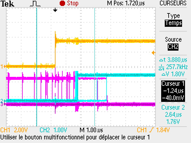
    I'll explain a bit more the oscilloscope screen: 

    In yellow, it corresponds to a debug pin used in the C2000, the pin is set in my ADC IT function just before setting the GPIO12, GPIO12 is toggled so it's more complicated to observe this gpio (the gpio IT in the C6000 is set to fire on both edge). But It checked that the gpio was correctly toggled, and it's fine, the toggle appears like 100ns after it is set and it's really stable. 

    The fall is not really relevant with the problem, it corresponds to the end of the calculation done in the C2000 after the return of data from the C6000.

    In blue, it correspond to a pin set in the GPIO interrupt function (1st thing done in the function), and the fall correspond to the end of the GPIO interrupt function. This interrupt function is really long but it is the only function that have top priority and shouldn't be stop or delayed. Again the fall of the signal is not relevant with the problem. 

    On the previous test there was no gpio set/fall in the timer IT function. I just did the test: 

    In blue and yellow: same as previous test

    In purple: debug gpio set when entering timer IT function, cleared when leaving timer IT function

    I observed on the oscilloscope that the shifting of the blue signal occured when the purple signal appears just before the rising of the blue one. the shifting has a duration of about 3.9µs

    I hope this reply will answer your questions. 

    I'll try during the day to test if the change of gpio or timer make any difference. 

    Regards, 

    Clément

  • Hi, 

    quick update on tests I made: 

    I tested with the interrupt on GPIO9 instead of GPIO12 => same jitter 

    I tested with the timer 8 instead of timer 0 => same jitter 

    I tested with the GPIO IT function with INT4 to have the higher priority possible => same jitter 

    Regards, 

    Clément

  • Hi,

    Thanks for the clarification! It means that for the two interrupts on C66x side, one is timer ISR with lower priority and the other is GPIO interrupt with higher priority, and both ISR set a pin respectively. In theory, the GPIO interrupt should not be delayed (the gap between yellow and blue line shouldn't be pushed bigger when purple line presenting in front).

    Given you both operate on certain GPIO pins, is it possible that the issue come from setting GPIO pin high itself, just a guess.

    1) In the timer ISR, if you don't toggle a debug GPIO pin, just do some arbitrary math (so you have a flat purple line), will you see any "shifting has a duration of about 3.9us" of the blue line? If yes, then it means that interrupt priority doesn't work. If no, that means driving GPIO has some artifacts, e.g. the circuit takes some time to set a new pin after setting a previous pin.

    2) In the timer ISR, if you keep the debug GPIO high longer enough into the GPIO interrupt, that is, not small spike in the purple line, but a long purple line toggled in high without existing when GPIO interrupt came in, do you see the blue line is shifted to the same 3.9us amount? If yes, that means interrupt priority still worked. 

    Regards, Eric    

  • Hi Eric, 

    1) The debug gpio was used in the gpio function interrupt, so I always had this shifting problem even when the debug gpio is not used in the timer function, the 1st oscilloscope screenshot corresponds to this test. For me it's not a GPIO driving problem. I think it's more because of the interrupt itself.

    Do you know how much time an interrupt function needs to save its context (data, registers...) when an interrupt with a higher priority preempts the current IT function ?

    2) Not sure I really get what you meant, the test is to rise the gpio in the timer IT function and to clear it the gpio it function, right ? 

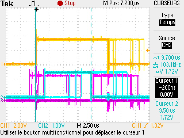
    I did this test, it's not easy to observe because I have to let the oscilloscope on infinite persistence to catch the phenomenon: 

    In blue and yellow: same as previous test

    In purple: debug gpio set when entering timer IT function, cleared when entering GPIO IT function

    The GPIO is cleared when entering the function and we can see the shifting. 

    I thought of another test (maybe it's the one you really wanted), I added some delay in the timer IT function to check if something appears: 

    In blue and yellow: same as previous test

    In purple: debug gpio set when entering timer IT function, cleared when leaving timer IT function

    The timer IT fired just before the GPIO IT are not preempted by the GPIO IT, so the gpio function IT is shifted. The purple signals on the right reveals that the timer IT wait for the end of the gpio IT to start (in normal operation, the blue signal falls at the place of the right cursor)

    It feels like the µC waits for the IT function to be over before starting a new IT function, and not priority matters. Is there a register to activate the pre-emption of high priority interrupt ? 

    regards, 

    Clement

  • Hi,

    It feels like the µC waits for the IT function to be over before starting a new IT function, and not priority matters. Is there a register to activate the pre-emption of high priority interrupt ? ======> Please see: https://e2e.ti.com/support/processors/f/791/t/226948 

    and https://processors.wiki.ti.com/index.php/Configuring_Interrupts_on_Keystone_Devices, searching for "nest".

    You need a OS to do interrupt pre-empt, the SYSBIOS can do this and switching latency needs several hundred CPU cycles. 

    Regards, Eric

  • Hi Eric, 

    thank you for your answer, I thought the nesting was hardarware on this DSP, my bad. 

    I still can't explain why my 100ns timer interrupt function shifts my GPIO IT function this much. But if the nesting resolves the problem, I'll be fine with it. 

    Regards, 

    Clément Leyssene