This thread has been locked.

If you have a related question, please click the "Ask a related question" button in the top right corner. The newly created question will be automatically linked to this question.

CCS/MSP430F5438A: CCS MSP430F5438A debug code with a calculated CRC32

Tool/software: Code Composer Studio

Again a question about the checksum generation (CRC). As I have recognized CRC calculation is not supported by the linker tool set as it was with the IAR Embedded Workbench. There I could just say:

  • Fill pattern: 0xff
  • CRC32: (0x4C11DB7)

and that was it.

IAR workbench:
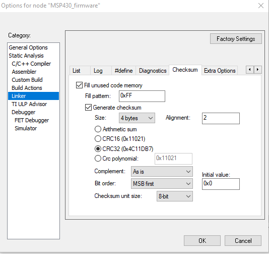
 

 The debug and release output consists of this CRC. Now with the CCS there is no such option to generate the CRC. But I read that SRecord does the same job for HEX files. I just put that to a post processing job of Eclipse CCS. That is fine for me but, when I want to generate debug code, and the CRC is not been calculated then my bootloader will not at all start the application code.

How can I fill the CRC (best with the same polynome: 0x4C11DB7) into the debug binary that CCS compiles

  • The CCS linker can generate CRC tables. I don't know if this is available as a CCS option. That polynomial looks like CRC32_PRIME.

    See also:

    https://e2e.ti.com/support/microcontrollers/msp430/f/166/p/829666/3068654

  • The linker, from the TI MSP430 compiler toolset, supports computing the CRC value across an output section and puts it in memory for later use by the program.  It is implemented by making changes to the linker command file.  That is, no changes are made to the CCS project settings.  Please search the MSP430 assembly tools manual for the sub-chapter titled Linker-Generated CRC Tables.  

    Thanks and regards,

    -George 

  • Thanks George, that works for me. I have generated the Tables with the linker and can also access that. 

    Two more questions I have with that. I have added another section in the linker file:

    MEMORY
    {
    
    ....
    
    CHECKSUM : origin = 0x5C00, length = 0x0020
    FLASH : origin = 0x5C20, length = 0xA360
    FLASH2 : origin = 0x10000,length = 0x35C00
    ....
    
    SECTIONS
    {
    #ifndef __LARGE_DATA_MODEL__
        .text       : {} >> FLASH2 | FLASH , crc_table(my_crc_table, algorithm=CRC32_PRIME)     /* Code  
    ....
    .TI.crctab : {} > CHECKSUM
    ....

    The CRC is only generated for the FLASH2 but not for FLASH. I know there is a hole in between those two sections, but how do I tell the linker to go through both of the sections to have an overall checksum?

    Also unclear is how do I set the start-value for the CRC32_PRIME calculation....

  • Marco Steinborn said:
    how do I tell the linker to go through both of the sections to have an overall checksum?

    The CRC tables auto-generated by the linker have this structure ...

    /****************************************************************************/
    /* CRC Record Data Structure                                                */
    /* NOTE: The list of fields and the size of each field varies by target     */
    /*       and memory model.                                                  */
    /****************************************************************************/
    typedef struct crc_record
    {
       uint32_t         crc_value;
       uint16_t         crc_alg_ID;  /* CRC algorithm ID                        */
       uintptr_t        addr;        /* Starting address                        */
    #if defined(__LARGE_CODE_MODEL__) || defined(__LARGE_DATA_MODEL__)
       uint32_t         size;        /* size of data in 8-bit addressable units */
    #else
       uint16_t         size;        /* size of data in 8-bit addressable units */
    #endif
    } CRC_RECORD;
    
     
    /**********************************************************/
    /* CRC Table Data Structure                               */
    /**********************************************************/
    typedef struct crc_table
    {
       uint16_t         rec_size;    /* 8-bit addressable units */
       uint16_t         num_recs;
       CRC_RECORD       recs[1];
    } CRC_TABLE;
    

    This code comes from the file crc_table.h, which is in the \include directory of the compiler installation.  Notice how a CRC_TABLE contains an array of CRC_RECORD.  A discontinuity in the memory range of the CRC check is handled by ending one CRC_RECORD and starting another.  

    Search the MSP430 assembly tools manual for an appendix titled Linker-Generated Copy Tables and CRC Tables.  It contains example code for checking the CRC based on tables created by the linker.  Search that example code for the function my_check_CRC.  Notice how this function goes through the array of CRC_RECORD's.

    Your CRC check has to work in a similar manner.

    Marco Steinborn said:
    how do I set the start-value for the CRC32_PRIME calculation

    I lack the expertise to answer.  If your device has HW support for computing the CRC, you should use it, and configure the linker CRC tables to match how it works.  This detail is best handled by MSP430 device experts.  Perhaps they have some examples to share.  I suggest you start a new thread in the MSP430 device forum.  Or, if you prefer, I can move this thread into that forum.

    Thanks and regards,

    -George

  • The structure of the crc_table I have checked and there is only one CRC_RECORD. Even though in the .cmd file 

    ...
    .text       : {} >> FLASH2 | FLASH, crc_table(linker_crc_table, algorithm=CRC32_PRIME)      /* Code  
    ...

    both memory areas are specified. So I would expect to have at least two records means one for FLASH and one for FLASH2. When I check the start my_crc_table.recs->start_value, it  points to the FLASH2.

    MEMORY
    {
    ...
        CHECKSUM		    : origin = 0x5C00, length = 0x0060 /* bit more space for two CRC record tables*/
        FLASH                   : origin = 0x5C60, length = 0xA320
        FLASH2                  : origin = 0x10000,length = 0x35C00
    ...

    In general I would have at least two records in the table or a combined CRC for both memory areas (.text). Do you have another idea? Thanks for your great help so far!!!

  • The split operation ...

    Marco Steinborn said:
    .text       : {} >> FLASH2 | FLASH

    ... means the linker is allowed to split the section as needed.  It does not guarantee a split.  If all of the .text section allocates into FLASH2, then no split occurs.  Is that the case here?  You can see it in the linker map file.

    Thanks and regards,

    -George

  • [Edit: Removed. George said it right.]

  • [Edit: Removed. George said it right.]

  • So a split is not guaranteed, I did some more playing around....

    I just filled the memory with some 0xff

    /* linker file */
    ...
        FLASH                   : origin = 0x5C60, length = 0xA320  ,fill = 0xffff
        FLASH2                  : origin = 0x10000,length = 0x35C00 ,fill = 0xffff
    
    ...

    , so I guess the linker has to set up a second record for the CRC, but it did not. Also I have created large arrays in the FLASH to shift the application into the FLASH2. Also the linker does not create a second record.

    How can I convince the linker to just calculate a CRC over two memory blocks? (or at least FLASH and FLASH2 separately, to calculate an overall sum later) Is it really that hard? Did nobody do that before? I just need to generate a checksum over the ROM area in the same way the IAR did before, but it seems impossible. Sorry I am not so deep into this linker scripting.

  • Please read through the first part of the article Linker Command File Primer, and get a clear understanding of the terms output section and memory range.  I'll use those terms throughout this post.

    Marco Steinborn said:
    How can I convince the linker to just calculate a CRC over two memory blocks?

    Remember that the linker does not compute the CRC over a memory range.  It computes it over a single output section.  That output section is often contained within one memory range.  But, because of possible section splitting, it may span multiple memory ranges.

    This contrived example demonstrates one CRC being computed on an output section that is split.  Here is the linker command file ...

    MEMORY
    {
       R1 : o = 0x1000, l = 0x100
       R2 : o = 0x2000, l = 0x8000
    }
    
    SECTIONS
    {
       .text >> R1 | R2, crc_table(my_crc_table)
    }

    The first memory range is much smaller, but appears first in the split.  That combination forces a section split to occur.

    I built a non-trivial program which uses that linker command file.  Here is the entry in the map file which describes the CRC table entry ...

    LINKER GENERATED CRC TABLES
    
    my_crc_table @ 00003072 records: 2, size/record: 10, table size: 24
    	.text.1: algorithm=CRC16_802_15_4(ID=1), load addr=00001000, size=00000100, CRC=000014e5
    	.text.2: algorithm=CRC16_802_15_4(ID=1), load addr=00002000, size=00000c3e, CRC=00006fa6
    

    If your .text section is split, you will see something similar.

    Thanks and regards,

    -George