This thread has been locked.

If you have a related question, please click the "Ask a related question" button in the top right corner. The newly created question will be automatically linked to this question.

CCS/CC1352P: Warning on force VDDR syscfg tool on CC9

Part Number: CC1352P

Tool/software: Code Composer Studio

Hi,

we use CC 9.3 and syscfg tool for configure our custom CC1352P board.

Of course, we need maximum output power on PA

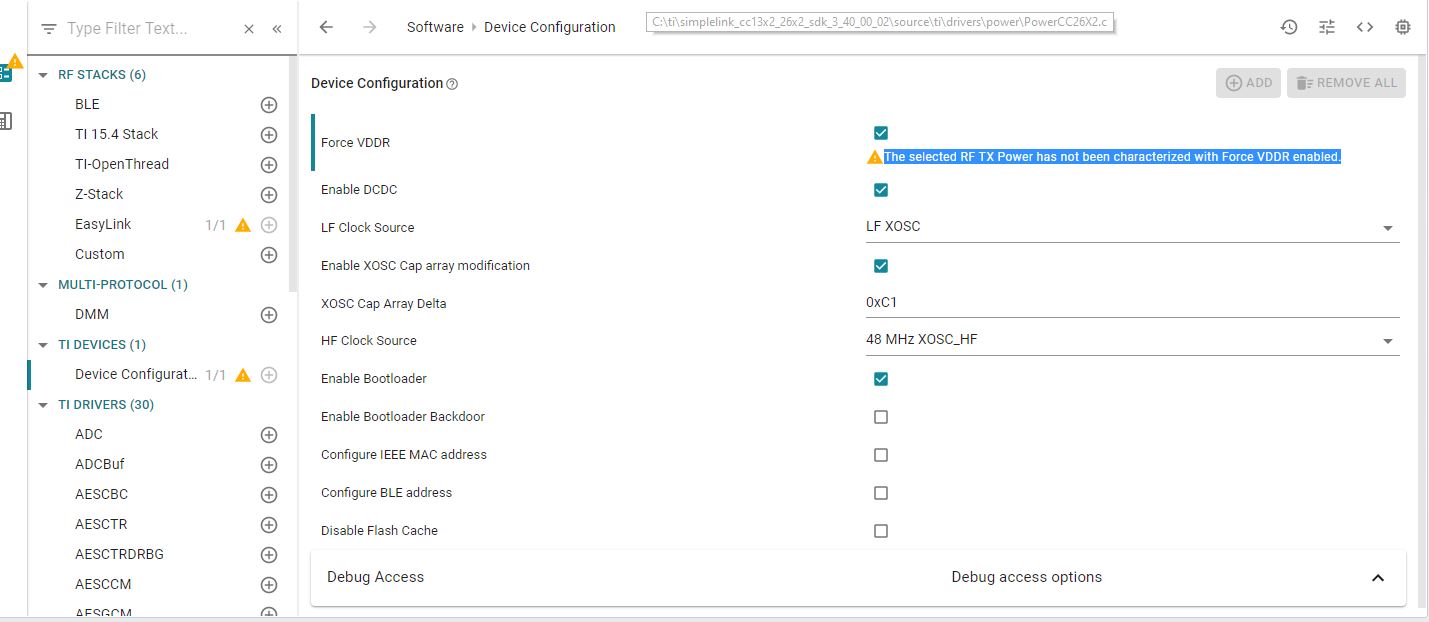
However, when setting force VDDR check box on syscfg tool , a warning appears: 

The selected RF TX Power has not been characterized with Force VDDR enabled, see snashot.

Not sure how to resolve it.


  • I have to check but:

    - Which example are you using (if any)

    - Could you show the settings you have changed from default to be able to recreate what you are seeing? 

  • Attached my syscfg.

    // These arguments were used when this file was generated. They will be automatically applied on subsequent loads 
    // via the GUI or CLI invocations. Run CLI with '--help' for additional information on how to override these arguments.
    // @cliArgs --device "CC1352P1F3RGZ" --package "RGZ" --part "Default" --product "simplelink_cc13x2_26x2_sdk@3.40.00.02"
    // @versions {"data":"2020022712","timestamp":"2020022712","tool":"1.3.1030","templates":"2020022712"}
    
    var RF = scripting.addModule("/ti/drivers/RF");
    var CCFG = scripting.addModule("/ti/devices/CCFG");
    var TRNG = scripting.addModule("/ti/drivers/TRNG");
    var TRNG1 = TRNG.addInstance();
    var easylink = scripting.addModule("/ti/easylink/easylink");
    var I2C = scripting.addModule("/ti/drivers/I2C", {}, false);
    var I2C1 = I2C.addInstance();
    var NVS = scripting.addModule("/ti/drivers/NVS", {}, false);
    var NVS1 = NVS.addInstance();
    var Timer = scripting.addModule("/ti/drivers/Timer", {}, false);
    var Timer1 = Timer.addInstance();
    var UART = scripting.addModule("/ti/drivers/UART", {}, false);
    var GPIO = scripting.addModule("/ti/drivers/GPIO", {}, false);
    var GPIO1 = GPIO.addInstance();
    var GPIO2 = GPIO.addInstance();
    var GPIO3 = GPIO.addInstance();
    var GPIO4 = GPIO.addInstance();
    var GPIO5 = GPIO.addInstance();
    var GPIO6 = GPIO.addInstance();
    var GPIO7 = GPIO.addInstance();
    var GPIO8 = GPIO.addInstance();
    var GPIO9 = GPIO.addInstance();
    var GPIO10 = GPIO.addInstance();
    var GPIO11 = GPIO.addInstance();
    var GPIO12 = GPIO.addInstance();
    var GPIO13 = GPIO.addInstance();
    var RTOS = scripting.addModule("/ti/drivers/RTOS");
    var UART1 = UART.addInstance();
    var UART2 = UART.addInstance();
    // Global Event Mask - Sets global RF driver events
    RF.globalEventMask = ["RF_GlobalEventRadioPowerDown","RF_GlobalEventRadioSetup"];
    // RF Pin Selection - Selects which pins are used by RF frontend
    RF.pinSelection = ["DIO_28","DIO_29","DIO_30"];
    // DIO_28
    RF.DIO_28 = "CONFIG_RF_24GHZ";
    // DIO_29
    RF.DIO_29 = "CONFIG_RF_HIGH_PA";
    // DIO_30
    RF.DIO_30 = "CONFIG_RF_SUB1GHZ";
    var Power = scripting.addModule("/ti/drivers/Power", {}, false);
    var Board = scripting.addModule("/ti/drivers/Board", {}, false);
    var DriverLib = scripting.addModule("/ti/devices/DriverLib", {}, false);
    // Assign pin
    RF.rfAntennaPin0.$assign = "DIO_30"; // pin number - 43
    // Assign pin
    RF.rfAntennaPin1.$assign = "DIO_29"; // pin number - 42
    // Assign pin
    RF.rfAntennaPin2.$assign = "DIO_28"; // pin number - 41
    // Enable XOSC Cap array modification - Enable modification (delta) to XOSC cap-array
    CCFG.xoscCapArray = true;
    // XOSC Cap Array Delta - Modify the high frequency oscillator cap-array, changing the frequency offset
    CCFG.xoscCapArrayDelta = 0xC1;
    // Enable Bootloader - Enable ROM Bootloader, for flashing from external host
    CCFG.enableBootloader = true;
    // Bootloader Backdoor DIO - DIO (pin) to trigger Bootloader backdoor, this pin is only needed at boot
    CCFG.dioBootloaderBackdoor = 15;
    // Trigger Level of Bootloader Backdoor - Active high or low on selected DIO to open boot loader backdoor
    CCFG.levelBootloaderBackdoor = "Active low";
    // Name
    CCFG.ccfgTemplate.$name = "ti_devices_CCFGTemplate0";
    // Name - The C/C++ identifier used in applications as the index parameter passed to TRNG runtime APIs
    TRNG1.$name = "CONFIG_TRNG_EASYLINK";
    // Random Number Generation Function - If a channel is busy, transmission will backoff for a random period. This function generates the random numbers for this functionality
    easylink.randNumGenFxn = "getRandomNumber";
    // Address Size (bytes) - Defines the address size used for all Tx/Rx operations
    easylink.addrSize = 2;
    // Addresses to Filter On (comma separated) - Defines the addresses this device will search for when receiving packets. Hex formatting.
    easylink.addrFilters = "";
    // Enable Address Filtering - Enables the stack to filter out addresses that are not in the address table provided
    easylink.enableAddrFilter = false;
    // Name
    easylink.radioConfigEasylinkPhyCustom.codeExportConfig.$name = "ti_devices_radioconfig_code_export_param0";
    var multi_stack_validate = scripting.addModule("/ti/easylink/multi_stack_validate", {}, false);
    // Name - The C/C++ identifier used in applications as the index parameter passed to I2C runtime APIs
    I2C1.$name = "CONFIG_I2C_0";
    // Name
    I2C1.i2c.$name = "MyI2C1";
    // Use Peripheral
    I2C1.i2c.$assign = "I2C0";
    // Assign pin
    I2C1.i2c.sdaPin.$assign = "DIO_5"; // pin number - 10
    // Assign pin
    I2C1.i2c.sclPin.$assign = "DIO_21"; // pin number - 31
    // Name
    I2C1.sdaPinInstance.$name = "CONFIG_PIN_0";
    // Name
    I2C1.clkPinInstance.$name = "CONFIG_PIN_1";
    // Name - The C/C++ identifier used in applications as the index parameter passed to NVS runtime APIs
    NVS1.$name = "CONFIG_NVS_0";
    // Name
    NVS1.internalFlash.$name = "ti_drivers_nvs_NVSCC26XX0";
    // Region Base - Base address of the region. Must be aligned on an integer multiple of the sector size.
    NVS1.internalFlash.regionBase = 0x48000;
    // Region Size - Size of the region in bytes. Must be a non-zero multiple of the Sector Size
    NVS1.internalFlash.regionSize = 0x8000;
    // Name - The C/C++ identifier used in applications as the index parameter passed to Timer runtime APIs
    Timer1.$name = "CONFIG_TIMER_0";
    // Name - The C/C++ identifier used in applications as the index parameter passed to GPTimerCC26XX runtime APIs
    Timer1.timerInstance.$name = "CONFIG_GPTIMER_0";
    // Name
    Timer1.timerInstance.timer.$name = "MyGPTM1";
    // Name - The C/C++ identifier used in applications as the index parameter passed to GPIO runtime APIs
    GPIO1.$name = "CONFIG_GPIO_BTN1";
    // Interrupt Trigger - Specifies when or if interrupts are triggered
    GPIO1.interruptTrigger = "Rising Edge";
    // Assign pin
    GPIO1.gpioPin.$assign = "DIO_27"; // pin number - 40
    // Name
    GPIO1.pinInstance.$name = "CONFIG_PIN_8";
    // Name - The C/C++ identifier used in applications as the index parameter passed to GPIO runtime APIs
    GPIO2.$name = "CONFIG_GPIO_INT_ACC";
    // Interrupt Trigger - Specifies when or if interrupts are triggered
    GPIO2.interruptTrigger = "Both Edges";
    // Assign pin
    GPIO2.gpioPin.$assign = "DIO_8"; // pin number - 14
    // Name
    GPIO2.pinInstance.$name = "CONFIG_PIN_9";
    // Name - The C/C++ identifier used in applications as the index parameter passed to GPIO runtime APIs
    GPIO3.$name = "CONFIG_GPIO_INT_AL";
    // Pull - Specifies the internal pull-up or pull-down resistor configuration of this GPIO pin.
    GPIO3.pull = "Pull Up";
    // Interrupt Trigger - Specifies when or if interrupts are triggered
    GPIO3.interruptTrigger = "Falling Edge";
    // Assign pin
    GPIO3.gpioPin.$assign = "DIO_9"; // pin number - 15
    // Name
    GPIO3.pinInstance.$name = "CONFIG_PIN_10";
    // Name - The C/C++ identifier used in applications as the index parameter passed to GPIO runtime APIs
    GPIO4.$name = "CONFIG_GPIO_INT_VOX";
    // Interrupt Trigger - Specifies when or if interrupts are triggered
    GPIO4.interruptTrigger = "Both Edges";
    // Assign pin
    GPIO4.gpioPin.$assign = "DIO_10"; // pin number - 16
    // Name
    GPIO4.pinInstance.$name = "CONFIG_PIN_11";
    // Name - The C/C++ identifier used in applications as the index parameter passed to GPIO runtime APIs
    GPIO5.$name = "CONFIG_GPIO_INT_EXPANDER";
    // Interrupt Trigger - Specifies when or if interrupts are triggered
    GPIO5.interruptTrigger = "Both Edges";
    // Assign pin
    GPIO5.gpioPin.$assign = "DIO_18"; // pin number - 28
    // Name
    GPIO5.pinInstance.$name = "CONFIG_PIN_12";
    // Name - The C/C++ identifier used in applications as the index parameter passed to GPIO runtime APIs
    GPIO6.$name = "CONFIG_GPIO_FS_VBUS";
    // Interrupt Trigger - Specifies when or if interrupts are triggered
    GPIO6.interruptTrigger = "Both Edges";
    // Assign pin
    GPIO6.gpioPin.$assign = "DIO_26"; // pin number - 39
    // Name
    GPIO6.pinInstance.$name = "CONFIG_PIN_13";
    // Name - The C/C++ identifier used in applications as the index parameter passed to GPIO runtime APIs
    GPIO7.$name = "CONFIG_GPIO_SENS_IN_BF";
    // Interrupt Trigger - Specifies when or if interrupts are triggered
    GPIO7.interruptTrigger = "Rising Edge";
    // Assign pin
    GPIO7.gpioPin.$assign = "DIO_22"; // pin number - 32
    // Name
    GPIO7.pinInstance.$name = "CONFIG_PIN_14";
    // Name - The C/C++ identifier used in applications as the index parameter passed to GPIO runtime APIs
    GPIO8.$name = "CONFIG_GPIO_SENS_IN_BF2";
    // Interrupt Trigger - Specifies when or if interrupts are triggered
    GPIO8.interruptTrigger = "Falling Edge";
    // Assign pin
    GPIO8.gpioPin.$assign = "DIO_15"; // pin number - 21
    // Name
    GPIO8.pinInstance.$name = "CONFIG_PIN_15";
    // Name - The C/C++ identifier used in applications as the index parameter passed to GPIO runtime APIs
    GPIO9.$name = "CONFIG_GPIO_INT_TILT";
    // Pull - Specifies the internal pull-up or pull-down resistor configuration of this GPIO pin.
    GPIO9.pull = "Pull Up";
    // Interrupt Trigger - Specifies when or if interrupts are triggered
    GPIO9.interruptTrigger = "Falling Edge";
    // Assign pin
    GPIO9.gpioPin.$assign = "DIO_14"; // pin number - 20
    // Name
    GPIO9.pinInstance.$name = "CONFIG_PIN_16";
    // Name - The C/C++ identifier used in applications as the index parameter passed to GPIO runtime APIs
    GPIO10.$name = "CONFIG_GPIO_INT_RTC";
    // Pull - Specifies the internal pull-up or pull-down resistor configuration of this GPIO pin.
    GPIO10.pull = "Pull Up";
    // Interrupt Trigger - Specifies when or if interrupts are triggered
    GPIO10.interruptTrigger = "Falling Edge";
    // Assign pin
    GPIO10.gpioPin.$assign = "DIO_25"; // pin number - 38
    // Name
    GPIO10.pinInstance.$name = "CONFIG_PIN_17";
    // Name - The C/C++ identifier used in applications as the index parameter passed to GPIO runtime APIs
    GPIO11.$name = "CONFIG_GPIO_BAT_OFF";
    // Mode - Select the GPIO mode
    GPIO11.mode = "Output";
    // Output Strength - Specifies the output strength
    GPIO11.outputStrength = "High";
    // Assign pin
    GPIO11.gpioPin.$assign = "DIO_23"; // pin number - 36
    // Name
    GPIO11.pinInstance.$name = "CONFIG_PIN_18";
    // Mode - Select the GPIO mode
    GPIO12.mode = "Output";
    // Name - The C/C++ identifier used in applications as the index parameter passed to GPIO runtime APIs
    GPIO12.$name = "CONFIG_GPIO_VEXT_EN";
    // Assign pin
    GPIO12.gpioPin.$assign = "DIO_20"; // pin number - 30
    // Name
    GPIO12.pinInstance.$name = "CONFIG_PIN_19";
    // Name - The C/C++ identifier used in applications as the index parameter passed to GPIO runtime APIs
    GPIO13.$name = "CONFIG_GPIO_CEL_PWRON";
    // Mode - Select the GPIO mode
    GPIO13.mode = "Output";
    // Initial Output State - Specifies the initial output state
    GPIO13.initialOutputState = "High";
    // Assign pin
    GPIO13.gpioPin.$assign = "DIO_11"; // pin number - 17
    // Name
    GPIO13.pinInstance.$name = "CONFIG_PIN_20";
    // Name - The C/C++ identifier used in applications as the index parameter passed to UART runtime APIs
    UART1.$name = "CONFIG_UART_1";
    // Flow Control - Enable hardware flow control
    UART1.flowControl = true;
    // Name
    UART1.txPinInstance.$name = "CONFIG_PIN_4";
    // Name
    UART1.rxPinInstance.$name = "CONFIG_PIN_5";
    // Name
    UART1.uart.$name = "MyUART1";
    // Use Peripheral
    UART1.uart.$assign = "UART1";
    // Assign pin
    UART1.uart.txPin.$assign = "DIO_24"; // pin number - 37
    // Assign pin
    UART1.uart.rxPin.$assign = "DIO_19"; // pin number - 29
    // Assign pin
    UART1.uart.ctsPin.$assign = "DIO_6"; // pin number - 11
    // Assign pin
    UART1.uart.rtsPin.$assign = "DIO_7"; // pin number - 12
    // Name
    UART1.ctsPinInstance.$name = "CONFIG_PIN_6";
    // Name
    UART1.rtsPinInstance.$name = "CONFIG_PIN_7";
    // Name - The C/C++ identifier used in applications as the index parameter passed to UART runtime APIs
    UART2.$name = "CONFIG_UART_0";
    // Name
    UART2.uart.$name = "MyUART1";
    // Use Peripheral
    UART2.uart.$assign = "UART0";
    // Assign pin
    UART2.uart.txPin.$assign = "DIO_13"; // pin number - 19
    // Assign pin
    UART2.uart.rxPin.$assign = "DIO_12"; // pin number - 18
    // Name
    UART2.txPinInstance.$name = "CONFIG_PIN_2";
    // Name
    UART2.rxPinInstance.$name = "CONFIG_PIN_3";
    // Suggest solution
    Timer1.timerInstance.timer.$suggestSolution = "GPTM0";
    

  • Sorry for the delay.

    It looks from your settings that you have selected 20 dBm output power and this setting is characterized with VDDR = 1.67 V. The HPA does not use VDDR and hence you should not change this when using this PA.

  • So if i want to use PA with maximum output power , I should do as followed :

    • "High PA" checkbox - checked 
    • "Force VDDR" checkbox - Unchecked 

    It is bit confusing as the tip tool for "Force  VDDR" is : " necessary for maximum PA output power"  

  • I see what you mean. The comment should be changed some to make it clear that this is for the 14 dBm PA and not the HPA (20 dBm PA)

    Meaning that i you want 20 dBm out you should:

    • "High PA" checkbox - checked 
    • "Force VDDR" checkbox - Unchecked 

    but if you want 14 dBm (and not 12.5 dBm) you should on the other PA output

    • "Force VDDR" checkbox - Checked 

  • Thanks , It is clear now !