This thread has been locked.

If you have a related question, please click the "Ask a related question" button in the top right corner. The newly created question will be automatically linked to this question.

CCS/CC1352P: CC1352P / SimpleLink 3.40.00.02 - rfDriverCallbackCustom implementation

Part Number: CC1352P
Other Parts Discussed in Thread: SYSCONFIG, ,

Tool/software: Code Composer Studio

We have a custom board and therefore a custom .syscfg file .

Using SimpleLink SDK 3.40.00.02 ( Rev E silicon)

As such, we need to add rfDriverCallbackCustom() for antenna switch.

Since there is no reference for such function, Used as reference rfDriverCallback function  from SDK 2.30.00.45 ( Rec C silicon)

There are some functions which are workaround for Rev C., Not sure if required or can be removed for Rev E silicon.

/*
* ======== CC1352P_rfDriverCallback ========
* Sets up the antenna switch depending on the current PHY configuration.
* Truth table:
*
* Path DIO28 DIO29 DIO30
* =========== ===== ===== =====
* Sub-1 GHz 0->X 0->1 1->1
* 2.4 GHz 1->X 0->0 0->1
* Sub-1 GHz 20dBm 0->0 1->1 0->0
* 2.4 GHz 20dBm 0->1 0->0 0->0
*/


void rfDriverCallbackCustom(RF_Handle client, RF_GlobalEvent events, void *arg)
{
/* Local variable. */
bool sub1GHz = false;
uint8_t loDivider = 0;

uint32_t val=0;
/* Initialize front-end (will only be done once) */
initRfFrontendCustom();

/* Switch off all paths first. Needs to be done anyway in every sub-case below. */
PINCC26XX_setOutputValue(CONFIG_RF_DIO28, 0);
PINCC26XX_setOutputValue(CONFIG_RF_DIO29, 0);
PINCC26XX_setOutputValue(CONFIG_RF_DIO30, 0);

if (events & RF_GlobalEventRadioSetup) {
/* Decode the current PA configuration. */
RF_TxPowerTable_PAType paType = (RF_TxPowerTable_PAType)RF_getTxPower(client).paType;

/* Decode the generic argument as a setup command. */
RF_RadioSetup* setupCommand = (RF_RadioSetup*)arg;

switch (setupCommand->common.commandNo) {
case (CMD_RADIO_SETUP):
case (CMD_BLE5_RADIO_SETUP):
loDivider = RF_LODIVIDER_MASK & setupCommand->common.loDivider;

/* Sub-1GHz front-end. */
if (loDivider != 0) {
sub1GHz = true;
}
break;
case (CMD_PROP_RADIO_DIV_SETUP):
loDivider = RF_LODIVIDER_MASK & setupCommand->prop_div.loDivider;

/* Sub-1GHz front-end. */
if (loDivider != 0) {
sub1GHz = true;
}
break;
default:break;
}

if (sub1GHz) {
/* Sub-1 GHz */
if (paType == RF_TxPowerTable_HighPA) {
/* PA enable --> HIGH PA
* LNA enable --> Sub-1 GHz
*/
PINCC26XX_setMux(frontendPins, CONFIG_RF_DIO28, PINCC26XX_MUX_GPIO);
/* Note: RFC_GPO3 is a work-around because the RFC_GPO1 (PA enable signal) is sometimes not
de-asserted on CC1352 Rev A. */
PINCC26XX_setMux(frontendPins, CONFIG_RF_DIO29, PINCC26XX_MUX_RFC_GPO3);
PINCC26XX_setMux(frontendPins, CONFIG_RF_DIO30, PINCC26XX_MUX_RFC_GPO0);

PINCC26XX_setOutputValue(CONFIG_RF_DIO28, 0);
PINCC26XX_setOutputValue(CONFIG_RF_DIO29, 1);
PINCC26XX_setOutputValue(CONFIG_RF_DIO30, 0);

val = PINCC26XX_getOutputValue(CONFIG_RF_DIO28);
val = PINCC26XX_getOutputValue(CONFIG_RF_DIO29);
val = PINCC26XX_getOutputValue(CONFIG_RF_DIO30);
} else {
/* RF core active --> Sub-1 GHz */
PINCC26XX_setMux(frontendPins, CONFIG_RF_DIO28, PINCC26XX_MUX_GPIO);
PINCC26XX_setMux(frontendPins, CONFIG_RF_DIO29, PINCC26XX_MUX_GPIO);
PINCC26XX_setMux(frontendPins, CONFIG_RF_DIO30, PINCC26XX_MUX_GPIO);

PINCC26XX_setOutputValue(CONFIG_RF_DIO29, 1);
PINCC26XX_setOutputValue(CONFIG_RF_DIO30, 1);
}
} else {
/* 2.4 GHz */
if (paType == RF_TxPowerTable_HighPA)
{
/* PA enable --> HIGH PA
* LNA enable --> 2.4 GHz
*/
PINCC26XX_setMux(frontendPins, CONFIG_RF_DIO28, PINCC26XX_MUX_RFC_GPO0);
/* Note: RFC_GPO3 is a work-around because the RFC_GPO1 (PA enable signal) is sometimes not
de-asserted on CC1352 Rev A. */
PINCC26XX_setMux(frontendPins, CONFIG_RF_DIO29, PINCC26XX_MUX_RFC_GPO3);
PINCC26XX_setMux(frontendPins, CONFIG_RF_DIO30, PINCC26XX_MUX_GPIO);

PINCC26XX_setOutputValue(CONFIG_RF_DIO28, 1);
PINCC26XX_setOutputValue(CONFIG_RF_DIO29, 0);
PINCC26XX_setOutputValue(CONFIG_RF_DIO30, 0);


} else {
/* RF core active --> 2.4 GHz */
PINCC26XX_setMux(frontendPins, CONFIG_RF_DIO28, PINCC26XX_MUX_GPIO);
PINCC26XX_setMux(frontendPins, CONFIG_RF_DIO29, PINCC26XX_MUX_GPIO);
PINCC26XX_setMux(frontendPins, CONFIG_RF_DIO30, PINCC26XX_MUX_GPIO);

PINCC26XX_setOutputValue(CONFIG_RF_DIO29, 0);
PINCC26XX_setOutputValue(CONFIG_RF_DIO30, 1);

}
}
} else {
/* Reset the IO multiplexer to GPIO functionality */
PINCC26XX_setMux(frontendPins, CONFIG_RF_DIO28, PINCC26XX_MUX_GPIO);
PINCC26XX_setMux(frontendPins, CONFIG_RF_DIO29, PINCC26XX_MUX_GPIO);
PINCC26XX_setMux(frontendPins, CONFIG_RF_DIO30, PINCC26XX_MUX_GPIO);
}
}

  • Hi Amit,

    You can find a reference callback if you compile for example a DMM example for the "P" platform devices. The function is generated with SysConfig and can be foudn in the "ti_drivers_config.c" file.

    What I can tell you is that there workarounds remain in place up to this date, I'm unsure if the actual problem has been solved and they are just legacy, but I would not remove them for now. I will try to look further into this to see if they are still needed.

  • Thanks for quick reply.

    I have implemented accordingly ( Actually kept same rfDriverCallback() implementation from SDK 2.30.00.45, Just added "custom" postfix), However 

    we are facing an issue after switching to  SDK 3.40.00.02 ( Rev E silicon) from SDK 2.30.00.45 ( Rev C silicon).

    ( The new custom board version using Rev . Silicon, Old using Rev C )

    Although using same RF settings ( 50 kpbs, 2-GFSK , 25Khz deviation ) , Unable to view transmitted packets from our custom board using LAUNCHXL-CC1352P and smart RF studio Packet RX mode.

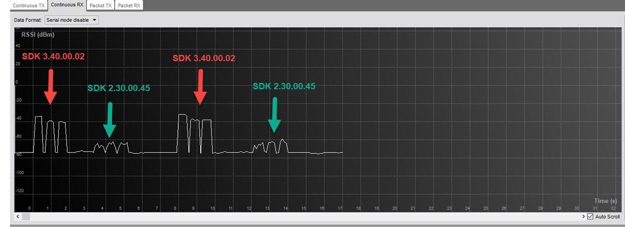
    Switched  to continuous RX mode on RF studio and Send packets from 2 custom board :

    - One using SDK 2.30.00.45 ( Rev C silicon)

    - Other using  SDK 3.40.00.02 ( Rev E silicon)

    You can see RSSI differences between two version. Attached new Rev E syscfg file 

  • MWR400 syscfg.txt
    // These arguments were used when this file was generated. They will be automatically applied on subsequent loads 
    // via the GUI or CLI invocations. Run CLI with '--help' for additional information on how to override these arguments.
    // @cliArgs --device "CC1352P1F3RGZ" --package "RGZ" --part "Default" --product "simplelink_cc13x2_26x2_sdk@3.40.00.02"
    // @versions {"data":"2020022712","timestamp":"2020022712","tool":"1.3.1030","templates":"2020022712"}
    
    var RF = scripting.addModule("/ti/drivers/RF");
    var CCFG = scripting.addModule("/ti/devices/CCFG");
    var TRNG = scripting.addModule("/ti/drivers/TRNG");
    var TRNG1 = TRNG.addInstance();
    var easylink = scripting.addModule("/ti/easylink/easylink");
    var I2C = scripting.addModule("/ti/drivers/I2C", {}, false);
    var I2C1 = I2C.addInstance();
    var NVS = scripting.addModule("/ti/drivers/NVS", {}, false);
    var NVS1 = NVS.addInstance();
    var Timer = scripting.addModule("/ti/drivers/Timer", {}, false);
    var Timer1 = Timer.addInstance();
    var UART = scripting.addModule("/ti/drivers/UART", {}, false);
    var GPIO = scripting.addModule("/ti/drivers/GPIO", {}, false);
    var GPIO1 = GPIO.addInstance();
    var GPIO2 = GPIO.addInstance();
    var GPIO3 = GPIO.addInstance();
    var GPIO4 = GPIO.addInstance();
    var GPIO5 = GPIO.addInstance();
    var GPIO6 = GPIO.addInstance();
    var GPIO7 = GPIO.addInstance();
    var GPIO8 = GPIO.addInstance();
    var GPIO9 = GPIO.addInstance();
    var GPIO10 = GPIO.addInstance();
    var GPIO11 = GPIO.addInstance();
    var GPIO12 = GPIO.addInstance();
    var GPIO13 = GPIO.addInstance();
    var RTOS = scripting.addModule("/ti/drivers/RTOS");
    var UART1 = UART.addInstance();
    var UART2 = UART.addInstance();
    // Global Event Mask - Sets global RF driver events
    RF.globalEventMask = ["RF_GlobalEventRadioPowerDown","RF_GlobalEventRadioSetup"];
    // RF Pin Selection - Selects which pins are used by RF frontend
    RF.pinSelection = ["DIO_28","DIO_29","DIO_30"];
    var Power = scripting.addModule("/ti/drivers/Power", {}, false);
    var Board = scripting.addModule("/ti/drivers/Board", {}, false);
    var DriverLib = scripting.addModule("/ti/devices/DriverLib", {}, false);
    // Assign pin
    RF.rfAntennaPin0.$assign = "DIO_30"; // pin number - 43
    // Assign pin
    RF.rfAntennaPin1.$assign = "DIO_29"; // pin number - 42
    // Assign pin
    RF.rfAntennaPin2.$assign = "DIO_28"; // pin number - 41
    // Enable XOSC Cap array modification - Enable modification (delta) to XOSC cap-array
    CCFG.xoscCapArray = true;
    // XOSC Cap Array Delta - Modify the high frequency oscillator cap-array, changing the frequency offset
    CCFG.xoscCapArrayDelta = 0xC1;
    // Enable Bootloader - Enable ROM Bootloader, for flashing from external host
    CCFG.enableBootloader = true;
    // Bootloader Backdoor DIO - DIO (pin) to trigger Bootloader backdoor, this pin is only needed at boot
    CCFG.dioBootloaderBackdoor = 15;
    // Trigger Level of Bootloader Backdoor - Active high or low on selected DIO to open boot loader backdoor
    CCFG.levelBootloaderBackdoor = "Active low";
    // Name
    CCFG.ccfgTemplate.$name = "ti_devices_CCFGTemplate0";
    // Name - The C/C++ identifier used in applications as the index parameter passed to TRNG runtime APIs
    TRNG1.$name = "CONFIG_TRNG_EASYLINK";
    // Random Number Generation Function - If a channel is busy, transmission will backoff for a random period. This function generates the random numbers for this functionality
    easylink.randNumGenFxn = "getRandomNumber";
    // Address Size (bytes) - Defines the address size used for all Tx/Rx operations
    easylink.addrSize = 2;
    // Addresses to Filter On (comma separated) - Defines the addresses this device will search for when receiving packets. Hex formatting.
    easylink.addrFilters = "";
    // Enable Address Filtering - Enables the stack to filter out addresses that are not in the address table provided
    easylink.enableAddrFilter = false;
    // Frequency (MHz) - Frequency.
    easylink.radioConfigEasylinkPhyCustom.carrierFrequency = 868.0000;
    // Packet Length Config - Packet Length Configuration
    easylink.radioConfigEasylinkPhyCustom.packetLengthConfig = "Variable";
    // Fixed Packet Length - The fixed packet length will not be part of the packet data.
    easylink.radioConfigEasylinkPhyCustom.fixedPacketLength = 30;
    // Name
    easylink.radioConfigEasylinkPhyCustom.codeExportConfig.$name = "ti_devices_radioconfig_code_export_param0";
    // PA table Export Method - Select how PA table is to be exported
    easylink.radioConfigEasylinkPhyCustom.codeExportConfig.paExport = "combined";
    var multi_stack_validate = scripting.addModule("/ti/easylink/multi_stack_validate", {}, false);
    // Name - The C/C++ identifier used in applications as the index parameter passed to I2C runtime APIs
    I2C1.$name = "CONFIG_I2C_0";
    // Name
    I2C1.i2c.$name = "MyI2C1";
    // Use Peripheral
    I2C1.i2c.$assign = "I2C0";
    // Assign pin
    I2C1.i2c.sdaPin.$assign = "DIO_5"; // pin number - 10
    // Assign pin
    I2C1.i2c.sclPin.$assign = "DIO_21"; // pin number - 31
    // Name
    I2C1.sdaPinInstance.$name = "CONFIG_PIN_0";
    // Name
    I2C1.clkPinInstance.$name = "CONFIG_PIN_1";
    // Name - The C/C++ identifier used in applications as the index parameter passed to NVS runtime APIs
    NVS1.$name = "CONFIG_NVS_0";
    // Name
    NVS1.internalFlash.$name = "ti_drivers_nvs_NVSCC26XX0";
    // Region Base - Base address of the region. Must be aligned on an integer multiple of the sector size.
    NVS1.internalFlash.regionBase = 0x48000;
    // Region Size - Size of the region in bytes. Must be a non-zero multiple of the Sector Size
    NVS1.internalFlash.regionSize = 0x8000;
    // Name - The C/C++ identifier used in applications as the index parameter passed to Timer runtime APIs
    Timer1.$name = "CONFIG_TIMER_0";
    // Name - The C/C++ identifier used in applications as the index parameter passed to GPTimerCC26XX runtime APIs
    Timer1.timerInstance.$name = "CONFIG_GPTIMER_0";
    // Name
    Timer1.timerInstance.timer.$name = "MyGPTM1";
    // Name - The C/C++ identifier used in applications as the index parameter passed to GPIO runtime APIs
    GPIO1.$name = "CONFIG_GPIO_BTN1";
    // Interrupt Trigger - Specifies when or if interrupts are triggered
    GPIO1.interruptTrigger = "Rising Edge";
    // Assign pin
    GPIO1.gpioPin.$assign = "DIO_27"; // pin number - 40
    // Name
    GPIO1.pinInstance.$name = "CONFIG_PIN_8";
    // Name - The C/C++ identifier used in applications as the index parameter passed to GPIO runtime APIs
    GPIO2.$name = "CONFIG_GPIO_INT_ACC";
    // Interrupt Trigger - Specifies when or if interrupts are triggered
    GPIO2.interruptTrigger = "Both Edges";
    // Assign pin
    GPIO2.gpioPin.$assign = "DIO_8"; // pin number - 14
    // Name
    GPIO2.pinInstance.$name = "CONFIG_PIN_9";
    // Name - The C/C++ identifier used in applications as the index parameter passed to GPIO runtime APIs
    GPIO3.$name = "CONFIG_GPIO_INT_AL";
    // Pull - Specifies the internal pull-up or pull-down resistor configuration of this GPIO pin.
    GPIO3.pull = "Pull Up";
    // Interrupt Trigger - Specifies when or if interrupts are triggered
    GPIO3.interruptTrigger = "Falling Edge";
    // Assign pin
    GPIO3.gpioPin.$assign = "DIO_9"; // pin number - 15
    // Name
    GPIO3.pinInstance.$name = "CONFIG_PIN_10";
    // Name - The C/C++ identifier used in applications as the index parameter passed to GPIO runtime APIs
    GPIO4.$name = "CONFIG_GPIO_INT_VOX";
    // Interrupt Trigger - Specifies when or if interrupts are triggered
    GPIO4.interruptTrigger = "Both Edges";
    // Assign pin
    GPIO4.gpioPin.$assign = "DIO_10"; // pin number - 16
    // Name
    GPIO4.pinInstance.$name = "CONFIG_PIN_11";
    // Name - The C/C++ identifier used in applications as the index parameter passed to GPIO runtime APIs
    GPIO5.$name = "CONFIG_GPIO_INT_EXPANDER";
    // Interrupt Trigger - Specifies when or if interrupts are triggered
    GPIO5.interruptTrigger = "Both Edges";
    // Assign pin
    GPIO5.gpioPin.$assign = "DIO_18"; // pin number - 28
    // Name
    GPIO5.pinInstance.$name = "CONFIG_PIN_12";
    // Name - The C/C++ identifier used in applications as the index parameter passed to GPIO runtime APIs
    GPIO6.$name = "CONFIG_GPIO_FS_VBUS";
    // Interrupt Trigger - Specifies when or if interrupts are triggered
    GPIO6.interruptTrigger = "Both Edges";
    // Assign pin
    GPIO6.gpioPin.$assign = "DIO_26"; // pin number - 39
    // Name
    GPIO6.pinInstance.$name = "CONFIG_PIN_13";
    // Name - The C/C++ identifier used in applications as the index parameter passed to GPIO runtime APIs
    GPIO7.$name = "CONFIG_GPIO_SENS_IN_BF";
    // Interrupt Trigger - Specifies when or if interrupts are triggered
    GPIO7.interruptTrigger = "Rising Edge";
    // Assign pin
    GPIO7.gpioPin.$assign = "DIO_22"; // pin number - 32
    // Name
    GPIO7.pinInstance.$name = "CONFIG_PIN_14";
    // Name - The C/C++ identifier used in applications as the index parameter passed to GPIO runtime APIs
    GPIO8.$name = "CONFIG_GPIO_SENS_IN_BF2";
    // Interrupt Trigger - Specifies when or if interrupts are triggered
    GPIO8.interruptTrigger = "Falling Edge";
    // Assign pin
    GPIO8.gpioPin.$assign = "DIO_15"; // pin number - 21
    // Name
    GPIO8.pinInstance.$name = "CONFIG_PIN_15";
    // Name - The C/C++ identifier used in applications as the index parameter passed to GPIO runtime APIs
    GPIO9.$name = "CONFIG_GPIO_INT_TILT";
    // Pull - Specifies the internal pull-up or pull-down resistor configuration of this GPIO pin.
    GPIO9.pull = "Pull Up";
    // Interrupt Trigger - Specifies when or if interrupts are triggered
    GPIO9.interruptTrigger = "Falling Edge";
    // Assign pin
    GPIO9.gpioPin.$assign = "DIO_14"; // pin number - 20
    // Name
    GPIO9.pinInstance.$name = "CONFIG_PIN_16";
    // Name - The C/C++ identifier used in applications as the index parameter passed to GPIO runtime APIs
    GPIO10.$name = "CONFIG_GPIO_INT_RTC";
    // Pull - Specifies the internal pull-up or pull-down resistor configuration of this GPIO pin.
    GPIO10.pull = "Pull Up";
    // Interrupt Trigger - Specifies when or if interrupts are triggered
    GPIO10.interruptTrigger = "Falling Edge";
    // Assign pin
    GPIO10.gpioPin.$assign = "DIO_25"; // pin number - 38
    // Name
    GPIO10.pinInstance.$name = "CONFIG_PIN_17";
    // Name - The C/C++ identifier used in applications as the index parameter passed to GPIO runtime APIs
    GPIO11.$name = "CONFIG_GPIO_BAT_OFF";
    // Mode - Select the GPIO mode
    GPIO11.mode = "Output";
    // Output Strength - Specifies the output strength
    GPIO11.outputStrength = "High";
    // Assign pin
    GPIO11.gpioPin.$assign = "DIO_23"; // pin number - 36
    // Name
    GPIO11.pinInstance.$name = "CONFIG_PIN_18";
    // Mode - Select the GPIO mode
    GPIO12.mode = "Output";
    // Name - The C/C++ identifier used in applications as the index parameter passed to GPIO runtime APIs
    GPIO12.$name = "CONFIG_GPIO_VEXT_EN";
    // Assign pin
    GPIO12.gpioPin.$assign = "DIO_20"; // pin number - 30
    // Name
    GPIO12.pinInstance.$name = "CONFIG_PIN_19";
    // Name - The C/C++ identifier used in applications as the index parameter passed to GPIO runtime APIs
    GPIO13.$name = "CONFIG_GPIO_CEL_PWRON";
    // Mode - Select the GPIO mode
    GPIO13.mode = "Output";
    // Initial Output State - Specifies the initial output state
    GPIO13.initialOutputState = "High";
    // Assign pin
    GPIO13.gpioPin.$assign = "DIO_11"; // pin number - 17
    // Name
    GPIO13.pinInstance.$name = "CONFIG_PIN_20";
    // Name - The C/C++ identifier used in applications as the index parameter passed to UART runtime APIs
    UART1.$name = "CONFIG_UART_1";
    // Flow Control - Enable hardware flow control
    UART1.flowControl = true;
    // Name
    UART1.txPinInstance.$name = "CONFIG_PIN_4";
    // Name
    UART1.rxPinInstance.$name = "CONFIG_PIN_5";
    // Name
    UART1.uart.$name = "MyUART1";
    // Use Peripheral
    UART1.uart.$assign = "UART1";
    // Assign pin
    UART1.uart.txPin.$assign = "DIO_24"; // pin number - 37
    // Assign pin
    UART1.uart.rxPin.$assign = "DIO_19"; // pin number - 29
    // Assign pin
    UART1.uart.ctsPin.$assign = "DIO_6"; // pin number - 11
    // Assign pin
    UART1.uart.rtsPin.$assign = "DIO_7"; // pin number - 12
    // Name
    UART1.ctsPinInstance.$name = "CONFIG_PIN_6";
    // Name
    UART1.rtsPinInstance.$name = "CONFIG_PIN_7";
    // Name - The C/C++ identifier used in applications as the index parameter passed to UART runtime APIs
    UART2.$name = "CONFIG_UART_0";
    // Name
    UART2.uart.$name = "MyUART1";
    // Use Peripheral
    UART2.uart.$assign = "UART0";
    // Assign pin
    UART2.uart.txPin.$assign = "DIO_13"; // pin number - 19
    // Assign pin
    UART2.uart.rxPin.$assign = "DIO_12"; // pin number - 18
    // Name
    UART2.txPinInstance.$name = "CONFIG_PIN_2";
    // Name
    UART2.rxPinInstance.$name = "CONFIG_PIN_3";
    // Suggest solution
    Timer1.timerInstance.timer.$suggestSolution = "GPTM0";
    

  • Hi Amit,

    Seems like the new board has better RF performance that the old one (or they are not running on the same frequency but close enough). Could you clarify the exact setup here in terms of TX -> RX test, did I understand it correctly like this:

    New custom board with rev. E and SDK 3.40 (TX) -> SmartRF Studio with CC1352P LaunchPad (Rev. E?) (RX)

    If this is correct, have a look into the generated output in the CCS project (SysConfig will put a few files under "Generated->SysConfig" where you can find the generated RF settings. Compare these settings of SmartRF Studio to see if they match each other (for example, is the frequency the same etc.). 

  • Hi ,

    As RX using LAUNCHXL-CC1352P1 .

    As TX , using our two custom CC1352P boards :

    • Old - SDK 2.30.00.45 ( Rev C silicon)
    • New - SDK 3.40.00.02 ( Rev E silicon)

    New board is exactly same as old except using Rev E silicon , so as a result we had to upgrade new SDK.

    After upgrading to new SDK , Unable to receive packets on  LAUNCHXL-CC1352P1.

    Using rev C silicon board, all worked perfectly. 

    Compared all settings and it looks ok.

  • Btw, There is a mistake on the continuous RX diagram above:

    - Old SDK 2.30.00.45 ( Rev C silicon) are the red arrow  ( High rssi)

    - New - SDK 3.40.00.02 ( Rev E silicon) are the green arrow ( Low rssi) 

  • What is the revision of the IC on the launchpad? 

    is the only change did to update SDK or did you also generate new RF settings etc for the project?

    If you run the "packet TX" example from the SDK, is the result the same?

    If you have two "new" boards, are these able to communicate if you run these with SmartRF Studio?

  • Hi M-W

    launchpad :

    • BOM Rev C
    • FW: SDK 3.2
    • 1930

    Using SDK 3.40.00.02  RF settings are generated via syscfg tool , not by RF studio.

    If I test two "new" boards they are able to communicate ( Although on RX Side calling EasyLink_getRssi(0 rsults in -128db) .

     Running ""packet TX"  example on new board result is the same -launchpad  packet RX fail to receive it. 

  • Hi Amit,

    You should be using a Rev. E launchpad as well, Rev C is pre-production silicon and I would expect that you can find differences in settings used between the SDKs.

    It is true that 3.40 has SysConfig but you could choose to use settings from RF Studio if you want to. No matter what, SysConfig should generate the same base line settings as SmartRF Studio (for the same revision IC).

    You seem to have a quite high noise floor where you work. which Easylink example are you running in this situation? I got the feeling that you were using proprietary commands directly and not Easylink?

  • Hi,

    1. I'm using REV .E launchpad.

       The launchpad BOM is Rev C , But silicon is Rev E. ( I was unable to use smartRF studio rev 2.16.0 unless it was Rev E silicon).

    2. Using EasyLink API , not proprietary commands.

  • That clarifies it the revision mix up :)

    Did you do a comparison of the setting used (like frequency) etc? Take the basic packetTX example instead of Easylink as it is easier to debug for now and simply build run, verify not working, and share the RF settings file that was generated as well as the settings used in Studio.

    It seems strange that your new boards would have lower signal strength than the new ones, have you made any effort to verify the antenna switching signals to see if these work as they should?

  • Hi,

    Just an update, Found root cause :

    XOSC cap array delta modification was derived from launchpad syscfg  , which its value 0xC1.

    After removing XOSC cap array delta modification (Un-check) for my custom board syscfg , problem is resolved.