This thread has been locked.

If you have a related question, please click the "Ask a related question" button in the top right corner. The newly created question will be automatically linked to this question.

CCS/CC1352P: EasyLink stack requires a Combined PA Table error

Part Number: CC1352P

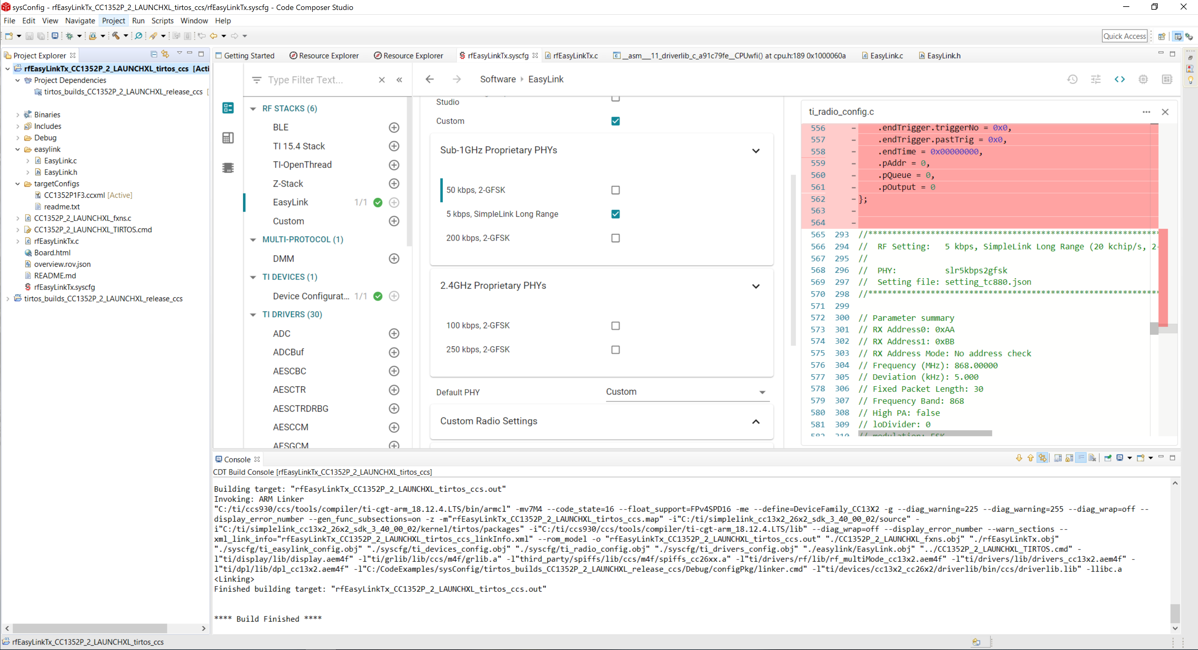
Tool/software: Code Composer Studio

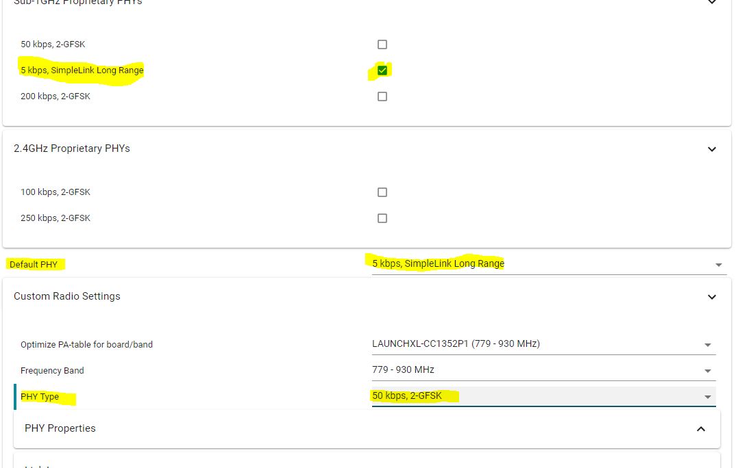
Tried to change syscfg EasyLink radio Sub 1Ghz PHYs to " 5 kbs, simplelink long range"

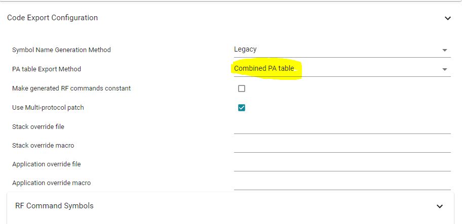
PA table export method is set to "combined PA table" , however still get compilation error:

subdir_rules.mk:26: recipe for target 'build-103578833-inproc' failed
error: /ti/easylink/easylink radioConfigEasylinkPhyCustom.codeExportConfig.paExport: EasyLink stack requires a Combined PA Table
1 error(s), 0 warning(s)

  • I am not sure I understand exactly what you have done.

    I took the rfEasyLinkTx example from the 3_40 SDK (using CC1352P-2) and changed the settings from 50 kbps to 5 kbps SLR by simply selecting this PHY (did not do any other changes):

    The project built without errors.

    BR

    Siri

  • Hi Siri,

    Changing the settings from 50 kbps to 5 kbps SLR by simply selecting this PHY on "RADIO" is not enough, and will not actually change the phy. 

    You need also to change the "custom PHY settings" to 5 kbps.

    Doing it will generate the error.

    Please double check

  • What version of the SDK and CCS are you using?

    Regards,
    Vegard

  • ccs :  Version: 9.3.0.00012 

    sdk:  SimpleLink 3.40.0.02

  • Can you share the .syscfg file here?

    Regards,
    Vegard

  • // These arguments were used when this file was generated. They will be automatically applied on subsequent loads 
    // via the GUI or CLI invocations. Run CLI with '--help' for additional information on how to override these arguments.
    // @cliArgs --device "CC1352P1F3RGZ" --package "RGZ" --part "Default" --product "simplelink_cc13x2_26x2_sdk@3.40.00.02"
    // @versions {"data":"2020022712","timestamp":"2020022712","tool":"1.3.1030","templates":"2020022712"}
    
    var RF = scripting.addModule("/ti/drivers/RF");
    var CCFG = scripting.addModule("/ti/devices/CCFG");
    var TRNG = scripting.addModule("/ti/drivers/TRNG");
    var TRNG1 = TRNG.addInstance();
    var easylink = scripting.addModule("/ti/easylink/easylink");
    var I2C = scripting.addModule("/ti/drivers/I2C", {}, false);
    var I2C1 = I2C.addInstance();
    var NVS = scripting.addModule("/ti/drivers/NVS", {}, false);
    var NVS1 = NVS.addInstance();
    var Timer = scripting.addModule("/ti/drivers/Timer", {}, false);
    var Timer1 = Timer.addInstance();
    var UART = scripting.addModule("/ti/drivers/UART", {}, false);
    var GPIO = scripting.addModule("/ti/drivers/GPIO", {}, false);
    var GPIO1 = GPIO.addInstance();
    var GPIO2 = GPIO.addInstance();
    var GPIO3 = GPIO.addInstance();
    var GPIO4 = GPIO.addInstance();
    var GPIO5 = GPIO.addInstance();
    var GPIO6 = GPIO.addInstance();
    var GPIO7 = GPIO.addInstance();
    var GPIO8 = GPIO.addInstance();
    var GPIO9 = GPIO.addInstance();
    var GPIO10 = GPIO.addInstance();
    var GPIO11 = GPIO.addInstance();
    var GPIO12 = GPIO.addInstance();
    var GPIO13 = GPIO.addInstance();
    var RTOS = scripting.addModule("/ti/drivers/RTOS");
    var UART1 = UART.addInstance();
    var UART2 = UART.addInstance();
    // Global Event Mask - Sets global RF driver events
    RF.globalEventMask = ["RF_GlobalEventRadioPowerDown","RF_GlobalEventRadioSetup"];
    // RF Pin Selection - Selects which pins are used by RF frontend
    RF.pinSelection = ["DIO_28","DIO_29","DIO_30"];
    var Power = scripting.addModule("/ti/drivers/Power", {}, false);
    var Board = scripting.addModule("/ti/drivers/Board", {}, false);
    var DriverLib = scripting.addModule("/ti/devices/DriverLib", {}, false);
    // Assign pin
    RF.rfAntennaPin0.$assign = "DIO_30"; // pin number - 43
    // Assign pin
    RF.rfAntennaPin1.$assign = "DIO_29"; // pin number - 42
    // Assign pin
    RF.rfAntennaPin2.$assign = "DIO_28"; // pin number - 41
    // Enable Bootloader - Enable ROM Bootloader, for flashing from external host
    CCFG.enableBootloader = true;
    // Bootloader Backdoor DIO - DIO (pin) to trigger Bootloader backdoor, this pin is only needed at boot
    CCFG.dioBootloaderBackdoor = 15;
    // Trigger Level of Bootloader Backdoor - Active high or low on selected DIO to open boot loader backdoor
    CCFG.levelBootloaderBackdoor = "Active low";
    // XOSC Cap Array Delta - Modify the high frequency oscillator cap-array, changing the frequency offset
    CCFG.xoscCapArrayDelta = 0x0;
    // Name
    CCFG.ccfgTemplate.$name = "ti_devices_CCFGTemplate0";
    // Name - The C/C++ identifier used in applications as the index parameter passed to TRNG runtime APIs
    TRNG1.$name = "CONFIG_TRNG_EASYLINK";
    // Random Number Generation Function - If a channel is busy, transmission will backoff for a random period. This function generates the random numbers for this functionality
    easylink.randNumGenFxn = "getRandomNumber";
    // Address Size (bytes) - Defines the address size used for all Tx/Rx operations
    easylink.addrSize = 2;
    // Addresses to Filter On (comma separated) - Defines the addresses this device will search for when receiving packets. Hex formatting.
    easylink.addrFilters = "";
    // Enable Address Filtering - Enables the stack to filter out addresses that are not in the address table provided
    easylink.enableAddrFilter = false;
    // 5 kbps, SimpleLink Long Range
    easylink.EasyLink_Phy_5kbpsSlLr = true;
    // Default PHY - The default PHY modulation to be used when EasyLink_init() is called
    easylink.defaultPhy = "EasyLink_Phy_5kbpsSlLr";
    // PHY Type - Selects the PHY/setting
    easylink.radioConfigEasylinkPhyCustom.phyType868 = "slr5kbps2gfsk";
    // Name
    easylink.radioConfigEasylinkPhyCustom.codeExportConfig.$name = "ti_devices_radioconfig_code_export_param0";
    var multi_stack_validate = scripting.addModule("/ti/easylink/multi_stack_validate", {}, false);
    // Name
    easylink.radioConfigEasylinkPhy5kbpssllr.codeExportConfig.$name = "ti_devices_radioconfig_code_export_param1";
    // Name - The C/C++ identifier used in applications as the index parameter passed to I2C runtime APIs
    I2C1.$name = "CONFIG_I2C_0";
    // Name
    I2C1.i2c.$name = "MyI2C1";
    // Use Peripheral
    I2C1.i2c.$assign = "I2C0";
    // Assign pin
    I2C1.i2c.sdaPin.$assign = "DIO_5"; // pin number - 10
    // Assign pin
    I2C1.i2c.sclPin.$assign = "DIO_21"; // pin number - 31
    // Name
    I2C1.sdaPinInstance.$name = "CONFIG_PIN_0";
    // Name
    I2C1.clkPinInstance.$name = "CONFIG_PIN_1";
    // Name - The C/C++ identifier used in applications as the index parameter passed to NVS runtime APIs
    NVS1.$name = "CONFIG_NVS_0";
    // Name
    NVS1.internalFlash.$name = "ti_drivers_nvs_NVSCC26XX0";
    // Region Base - Base address of the region. Must be aligned on an integer multiple of the sector size.
    NVS1.internalFlash.regionBase = 0x48000;
    // Region Size - Size of the region in bytes. Must be a non-zero multiple of the Sector Size
    NVS1.internalFlash.regionSize = 0x8000;
    // Name - The C/C++ identifier used in applications as the index parameter passed to Timer runtime APIs
    Timer1.$name = "CONFIG_TIMER_0";
    // Name - The C/C++ identifier used in applications as the index parameter passed to GPTimerCC26XX runtime APIs
    Timer1.timerInstance.$name = "CONFIG_GPTIMER_0";
    // Name
    Timer1.timerInstance.timer.$name = "MyGPTM1";
    // Name - The C/C++ identifier used in applications as the index parameter passed to GPIO runtime APIs
    GPIO1.$name = "CONFIG_GPIO_BTN1";
    // Interrupt Trigger - Specifies when or if interrupts are triggered
    GPIO1.interruptTrigger = "Rising Edge";
    // Assign pin
    GPIO1.gpioPin.$assign = "DIO_27"; // pin number - 40
    // Name
    GPIO1.pinInstance.$name = "CONFIG_PIN_8";
    // Name - The C/C++ identifier used in applications as the index parameter passed to GPIO runtime APIs
    GPIO2.$name = "CONFIG_GPIO_INT_ACC";
    // Interrupt Trigger - Specifies when or if interrupts are triggered
    GPIO2.interruptTrigger = "Both Edges";
    // Assign pin
    GPIO2.gpioPin.$assign = "DIO_8"; // pin number - 14
    // Name
    GPIO2.pinInstance.$name = "CONFIG_PIN_9";
    // Name - The C/C++ identifier used in applications as the index parameter passed to GPIO runtime APIs
    GPIO3.$name = "CONFIG_GPIO_INT_AL";
    // Pull - Specifies the internal pull-up or pull-down resistor configuration of this GPIO pin.
    GPIO3.pull = "Pull Up";
    // Interrupt Trigger - Specifies when or if interrupts are triggered
    GPIO3.interruptTrigger = "Falling Edge";
    // Assign pin
    GPIO3.gpioPin.$assign = "DIO_9"; // pin number - 15
    // Name
    GPIO3.pinInstance.$name = "CONFIG_PIN_10";
    // Name - The C/C++ identifier used in applications as the index parameter passed to GPIO runtime APIs
    GPIO4.$name = "CONFIG_GPIO_INT_VOX";
    // Interrupt Trigger - Specifies when or if interrupts are triggered
    GPIO4.interruptTrigger = "Both Edges";
    // Assign pin
    GPIO4.gpioPin.$assign = "DIO_10"; // pin number - 16
    // Name
    GPIO4.pinInstance.$name = "CONFIG_PIN_11";
    // Name - The C/C++ identifier used in applications as the index parameter passed to GPIO runtime APIs
    GPIO5.$name = "CONFIG_GPIO_INT_EXPANDER";
    // Interrupt Trigger - Specifies when or if interrupts are triggered
    GPIO5.interruptTrigger = "Both Edges";
    // Assign pin
    GPIO5.gpioPin.$assign = "DIO_18"; // pin number - 28
    // Name
    GPIO5.pinInstance.$name = "CONFIG_PIN_12";
    // Name - The C/C++ identifier used in applications as the index parameter passed to GPIO runtime APIs
    GPIO6.$name = "CONFIG_GPIO_FS_VBUS";
    // Interrupt Trigger - Specifies when or if interrupts are triggered
    GPIO6.interruptTrigger = "Both Edges";
    // Assign pin
    GPIO6.gpioPin.$assign = "DIO_26"; // pin number - 39
    // Name
    GPIO6.pinInstance.$name = "CONFIG_PIN_13";
    // Name - The C/C++ identifier used in applications as the index parameter passed to GPIO runtime APIs
    GPIO7.$name = "CONFIG_GPIO_SENS_IN_BF";
    // Interrupt Trigger - Specifies when or if interrupts are triggered
    GPIO7.interruptTrigger = "Rising Edge";
    // Assign pin
    GPIO7.gpioPin.$assign = "DIO_22"; // pin number - 32
    // Name
    GPIO7.pinInstance.$name = "CONFIG_PIN_14";
    // Name - The C/C++ identifier used in applications as the index parameter passed to GPIO runtime APIs
    GPIO8.$name = "CONFIG_GPIO_SENS_IN_BF2";
    // Interrupt Trigger - Specifies when or if interrupts are triggered
    GPIO8.interruptTrigger = "Falling Edge";
    // Assign pin
    GPIO8.gpioPin.$assign = "DIO_15"; // pin number - 21
    // Name
    GPIO8.pinInstance.$name = "CONFIG_PIN_15";
    // Name - The C/C++ identifier used in applications as the index parameter passed to GPIO runtime APIs
    GPIO9.$name = "CONFIG_GPIO_INT_TILT";
    // Pull - Specifies the internal pull-up or pull-down resistor configuration of this GPIO pin.
    GPIO9.pull = "Pull Up";
    // Interrupt Trigger - Specifies when or if interrupts are triggered
    GPIO9.interruptTrigger = "Falling Edge";
    // Assign pin
    GPIO9.gpioPin.$assign = "DIO_14"; // pin number - 20
    // Name
    GPIO9.pinInstance.$name = "CONFIG_PIN_16";
    // Name - The C/C++ identifier used in applications as the index parameter passed to GPIO runtime APIs
    GPIO10.$name = "CONFIG_GPIO_INT_RTC";
    // Pull - Specifies the internal pull-up or pull-down resistor configuration of this GPIO pin.
    GPIO10.pull = "Pull Up";
    // Interrupt Trigger - Specifies when or if interrupts are triggered
    GPIO10.interruptTrigger = "Falling Edge";
    // Assign pin
    GPIO10.gpioPin.$assign = "DIO_25"; // pin number - 38
    // Name
    GPIO10.pinInstance.$name = "CONFIG_PIN_17";
    // Name - The C/C++ identifier used in applications as the index parameter passed to GPIO runtime APIs
    GPIO11.$name = "CONFIG_GPIO_BAT_OFF";
    // Mode - Select the GPIO mode
    GPIO11.mode = "Output";
    // Output Strength - Specifies the output strength
    GPIO11.outputStrength = "High";
    // Assign pin
    GPIO11.gpioPin.$assign = "DIO_23"; // pin number - 36
    // Name
    GPIO11.pinInstance.$name = "CONFIG_PIN_18";
    // Mode - Select the GPIO mode
    GPIO12.mode = "Output";
    // Name - The C/C++ identifier used in applications as the index parameter passed to GPIO runtime APIs
    GPIO12.$name = "CONFIG_GPIO_VEXT_EN";
    // Assign pin
    GPIO12.gpioPin.$assign = "DIO_20"; // pin number - 30
    // Name
    GPIO12.pinInstance.$name = "CONFIG_PIN_19";
    // Name - The C/C++ identifier used in applications as the index parameter passed to GPIO runtime APIs
    GPIO13.$name = "CONFIG_GPIO_CEL_PWRON";
    // Mode - Select the GPIO mode
    GPIO13.mode = "Output";
    // Initial Output State - Specifies the initial output state
    GPIO13.initialOutputState = "High";
    // Assign pin
    GPIO13.gpioPin.$assign = "DIO_11"; // pin number - 17
    // Name
    GPIO13.pinInstance.$name = "CONFIG_PIN_20";
    // Name - The C/C++ identifier used in applications as the index parameter passed to UART runtime APIs
    UART1.$name = "CONFIG_UART_1";
    // Flow Control - Enable hardware flow control
    UART1.flowControl = true;
    // Name
    UART1.txPinInstance.$name = "CONFIG_PIN_4";
    // Name
    UART1.rxPinInstance.$name = "CONFIG_PIN_5";
    // Name
    UART1.uart.$name = "MyUART1";
    // Use Peripheral
    UART1.uart.$assign = "UART1";
    // Assign pin
    UART1.uart.txPin.$assign = "DIO_24"; // pin number - 37
    // Assign pin
    UART1.uart.rxPin.$assign = "DIO_19"; // pin number - 29
    // Assign pin
    UART1.uart.ctsPin.$assign = "DIO_6"; // pin number - 11
    // Assign pin
    UART1.uart.rtsPin.$assign = "DIO_7"; // pin number - 12
    // Name
    UART1.ctsPinInstance.$name = "CONFIG_PIN_6";
    // Name
    UART1.rtsPinInstance.$name = "CONFIG_PIN_7";
    // Name - The C/C++ identifier used in applications as the index parameter passed to UART runtime APIs
    UART2.$name = "CONFIG_UART_0";
    // Name
    UART2.uart.$name = "MyUART1";
    // Use Peripheral
    UART2.uart.$assign = "UART0";
    // Assign pin
    UART2.uart.txPin.$assign = "DIO_13"; // pin number - 19
    // Assign pin
    UART2.uart.rxPin.$assign = "DIO_12"; // pin number - 18
    // Name
    UART2.txPinInstance.$name = "CONFIG_PIN_2";
    // Name
    UART2.rxPinInstance.$name = "CONFIG_PIN_3";
    // Suggest solution
    Timer1.timerInstance.timer.$suggestSolution = "GPTM0";
    

  • Can you try to upgrade to CCS 10? I am not able to reproduce the problem on this version of CCS.

    Vegard

  • Hi,

    Seems it was resolved at CCS 10 , Thanks !