This thread has been locked.

If you have a related question, please click the "Ask a related question" button in the top right corner. The newly created question will be automatically linked to this question.

Compiler: EOG

Other Parts Discussed in Thread: INA333, OPA314, TPS735

Tool/software: TI C/C++ Compiler

Hi,

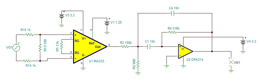
I've designed an EOG and now I try to simulate the analog part of the circuit. Do you have any suggestion, how I can simulate the electrodes?

To make it clear: 2 electrodes must be connected to pin2&3 of INA333 (U1) to follow the eye movement to the left & right and 2 other electrodes must be connected to pin2&3 of INA333 (U4) to follow up & down movement.

TNX

  • Hi 

    Question:

    how I can simulate the electrodes? (EOG)

    I think that EOG is similar to sine wave signal, but it is not continuous. I'd recommend to simulate it in sine wave with the highest frequency*10 may be seen in your application. You may have larger capacitive load at the op amp's output, and you need need to make sure that the EOG circuit is stable, not subject to any oscillation under various real world conditions.  

    /cfs-file/__key/communityserver-discussions-components-files/81/INA333-EOG-06012020.TSC

    From your schematic, it looks like that you are planning to use single voltage supply rail. Please pay attention to your common mode voltage and output voltage in the application. 

    BTW, what are you trying to do in OPA314 stage? 

    Best,

    Raymond

  • Hi Raymond,

    Thank you so much for your answer!

    Actually I have no idea what I should do because I have no experience choosing the appropriate component. 

    I don't know what should be taken into consideration from the datasheet.

    Can you please tell me what should I pay attention to when looking for components? I really want to learn how to design a circuit and choose the component. Can you please give me a reference?

    I didn't really understand what you mean by the picture.

    And I've used OPA314 to amplify the analog signal, which goes to the microcontroller to be converted to digital.

    I will appreciate it if you help me with that.

    Best Regard

    Mahdieh

  • Hi Mahdieh,

    I need the following design information from you. 

    1. EOG's input signal is typically from 50uV to 3.5mV, sine wave like from DC 50Hz. What is yours?

    2. TPS735 500-mA is low noise, High PSRR LDO  linear regulator, input voltage is from 2.7-6.5V. Output voltage is adjustable from 1.25V to 6V. I configured the simulation for 5V, which means your input voltage should be approx. 6Vdc. I need to know what is your intended supply voltage for the application, 3.3V, 5.0V. I assumed that the application is operating in a single voltage supply rail. 

    3. I need to configure your Sallen key low pass filter. I need to know your allowed highest frequency before the AC signal starts to attenuate, 61.45Hz? This is what is shown in the following schematic.

    4, What is desired output voltage amplitude before both signals are going to ADC? 

    Best,

    Raymond 

  • Hello Reymond,

    This is the block diagram of my project. 

    I use INA to amplify the signal from electrodes 10 times, then I use the Butterworth filter as bandpass (I chose it among the available bandpass filters of TI website).

    Now I need to simulate the analog part and write the result in my report, just showing the signals, when the eye moves horizontal or vertical.

    And as supply voltage I need  3.3 volts to activate the components.

    Is that clear now, what I am up to?

    Best Regards,

    Mahdieh

  • And I found out that I need only to simulate the horizontal or vertical movement because the circuit is the same. So I changed my design as follow:

  • Hi Mahdieh,

    The information you sent today is already understood from the earlier post. Now I know the following.

    Design Requirements.

    1. Operating voltages are 3.3V single voltage rails (from today's email). 

    2. It is for OEG, which means low frequency from 0-50Hz. 

    3. INA333's gain is 10.09. If your input signal is 50uV for low end, your output signal is only approx. 500uV --> is this adequate? In other words, is you ADC can measure this level of signal accurately? I think that you may need slightly higher gain. 

    Still Unknown about your design:

    1. You want to use Bandpass, what is the pass frequency range? please see the common filter shapes below. 

    2. What is your intended output voltage amplitude? 

    2. Your filter circuit does not behave the intended application, see the image below. Your filter circuit will block low frequency signal, pass high frequency at 154kHz, which is NOT what you want. I presented Low Pass Filter in my previous post, since this is EOG application, and your max, frequency response is approx. 50Hz or so. 

    Enclosed is common type of filters, please let me know which filter configuration is for your application. I picked Low_Pass filter for you in the previous post. 

    /cfs-file/__key/communityserver-discussions-components-files/81/OPA314-Filter.TSC

    Best,

    Raymond

  • Hi Mahdieh,

    Do you want to send me a friend request via E2E, if you want to keep the post private?

    I can help you to design the circuit, but you have to tell me what is the design requirements in details. 

    Best,

    Raymond

  • Hey Raymond,

    I use the ADC od microcontroller STM32L476RG and I found from the datasheet this: 12-bit ADC 5 Msps, up to 16-bit with hardware oversampling, 200 μA/Msps.

    Is it adequate?

    My supervisor just advised me to use a Bandpass.

    Best Wishes,

    Mahdieh

  • Hi Mahdieh,

    I am going to close this inquiry, since we have established communication via E2E private message. 

    Best,

    Raymond