This thread has been locked.

If you have a related question, please click the "Ask a related question" button in the top right corner. The newly created question will be automatically linked to this question.

CCS/LAUNCHXL-F28379D: CLB clocking

Part Number: LAUNCHXL-F28379D


Tool/software: Code Composer Studio

Hi

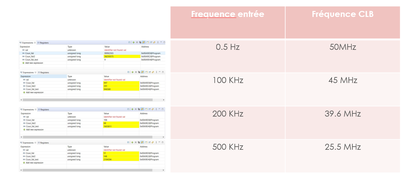
I'm working with the CLB module on LAUNCHXL-F28379D in order to detect the time stamp between two falling edges on a variable period PWM signal.

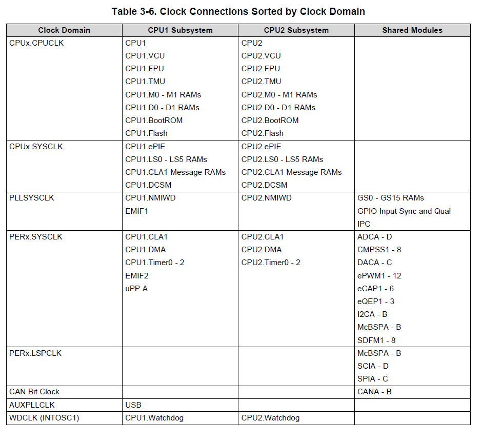
I'm trying to change the counter frequency but can't find neither a function in the c2000 firmware or the clocking source of themodule from the clocking chart in the data sheet.

  • The clock of the CLB Counter is the same as the CLB clock, which in this device is EPWM1 Clock. If you want to implement a divider, you can use a different counter module to implement a clock divider, then use the output of that counter as the input to either the enable/event signal of the next COUNTER module. 

    Nima

  • i wanna control the clock of the CLB in general and particulary the clock driving its counter ...

    my big issue is that inspecting the values of the counter (in an application that detects the period of different PWM signals) i found that the frequency of the counter is not the same for all the input PWM signals. Its frequency changes inversly propotinal with the rate of the input signal.

  • How did you change the freq of the CLB?

  • I didn't change the frequency of the CLB. I'm using its counter to return the period of different PWMinput signals.

    When I change the frequency of the input signals, the readings of the counter indicate that the frequency of the CLB is changing as well.

  • What are the signals which the CLB is measuring? The EPWM outputs or is the CTR=ZERO and CTR=PRD events?

    Basically what is the input to the CLB.

    Nima

  • PWM signals generated by an external source on a GPIO pin... Using the CLB's counter and FSM I can detect all the falling edges of these signals and then with an ISR I read the value of the counter register C0 at every falling edge  (which reprensents in my case the period of the input signals) and then reset the counter.

    The problem here is that the values of the counter are indicating that its frequency  is changing depending on the frequency of the input signals .. as indicating the screenshot above.

  • There must be an incorrect setting in the logic. 

    1. you can use the INPUT FILTER module, to create a pulse on EDGES, falling and rising edge.

    2. Share your designed logic's HTML block diagram

    Nima

  • Thank you the problem has  been resolved ....

    I discovered after a while that the values of the counter -indicating that the frequency of the block is changing- contained actually  a fixed error of 50 points ... This error varies depending on the length of the ISR which generates the signal that does the reset of  the counter ..

    So the transition between the CLB and the processor takes "apperently" long time.