Other Parts Discussed in Thread: TIDM-02002
Tool/software: Code Composer Studio
I'm working with the software released for the TIDM-02002 reference design, but I'm noticing that writes from the watch window in CCS seem to result in two 16 bit writes to the 32 bit floating point variable. One 16 bit write occurring before the variable is copied to another and the second 16 bit write occurring after the variable is copied.
Is this possible?
For more background:
The CLLLC_pwmPeriodRef_pu value is copied to the CLLLC_pwmPeriodSlewed_pu variable each time ISR2 is serviced. Whenever the value of CLLLC_pwmPeriodSlewed_pu changes, ISR1 will be triggered and the PWM frequency will be updated. The way that the bits are written from the watch window to the device memory seems to result in two updates of CLLLC_pwmPeriodRef_pu variable. It appears the 16 LSB of the CLLLC_pwmPeriodRef_pu value are written first, and then the 16 MSB. Between these two writes the CLLLC_pwmPeriodRef_pu value gets copied to the CLLLC_pwmPeriodSlewed_pu variable and the program treats the two writes as two separate updates, triggering the ISR1 twice.
I made three observations to support this:
- Changes to the CLLLC_pwmPeriodRef_pu variable originating from the code always result in one ISR1 call.
- I.e. only the watch window results in two calls.
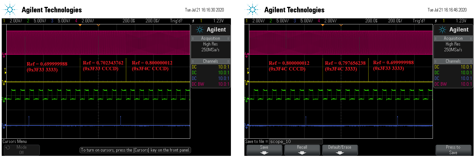
- I was able to observe the value of CLLLC_periodSlewed_pu between the two ISR calls and noticed only the 16 LSB were updating (see first set of scopeshots below).
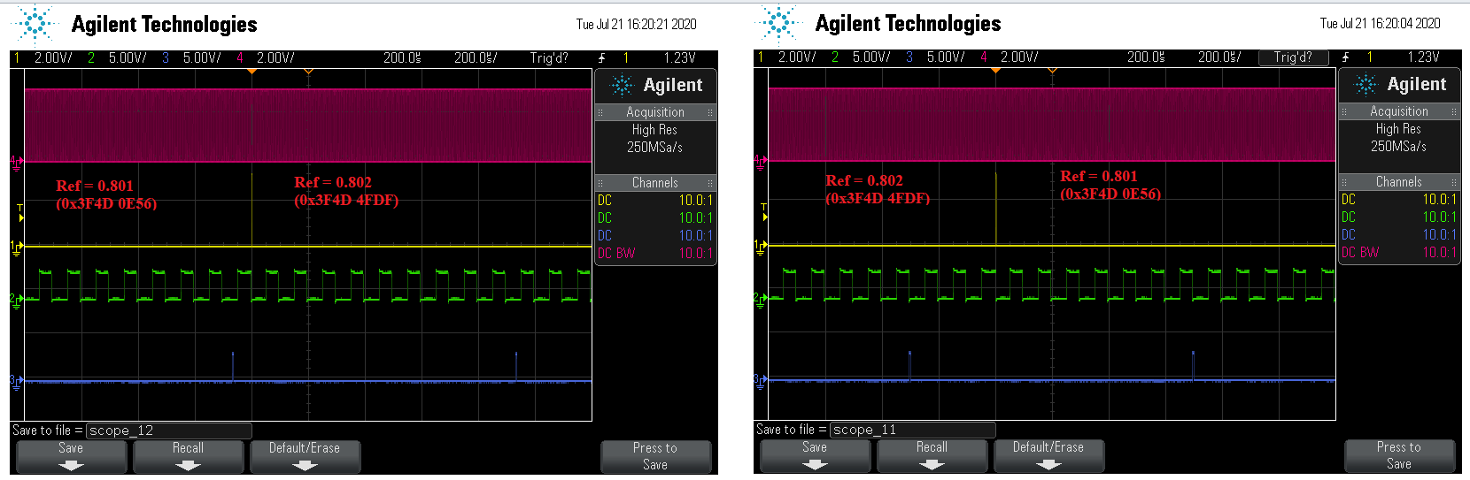
- Changing CLLLC_pwmPeriodRef_pu from the watch window by a small enough step that the 16 MSB don’t change always results in a single ISR1 call. (see second set of scopeshots below)
- E.g. CLLLC_pwmPeriodRef_pu = 0.801 <-> CLLLC_pwmPeriodRef_pu = 0.802 (0x3F4D0E56 <-> 0x3F4D4FDF)
Here are a couple scopeshots below to help illustrate my point. For debugging purposes, at the beginning of each ISR I assert a GPIO, at the end of the ISR I clear that GPIO.
(Yellow – ISR1, Green – ISR 2, Blue – ISR3, Red – PWM1A)