Part Number: MSP430FR2433
Tool/software: TI C/C++ Compiler
Hello
I currently have a micro that can read a number that is given by a user via a keypad. Then this number is sent via UART1 to my PC (Real Term). So far it all works just fine. No issues.
Now I want to send a code via PC (Real Term) to the micro as well. So I want to implement custom interrupt. The compiler spends most of its time in an infinite loop function called Keypad(); waiting for the user to press any button on the keypad. In this infinite loop, I implemented the following interrupt:
if(UCA1IV == 2) // if a character is received by the RX buffer
{OTA_code();} // call this function. This function will read the Rx buffer.
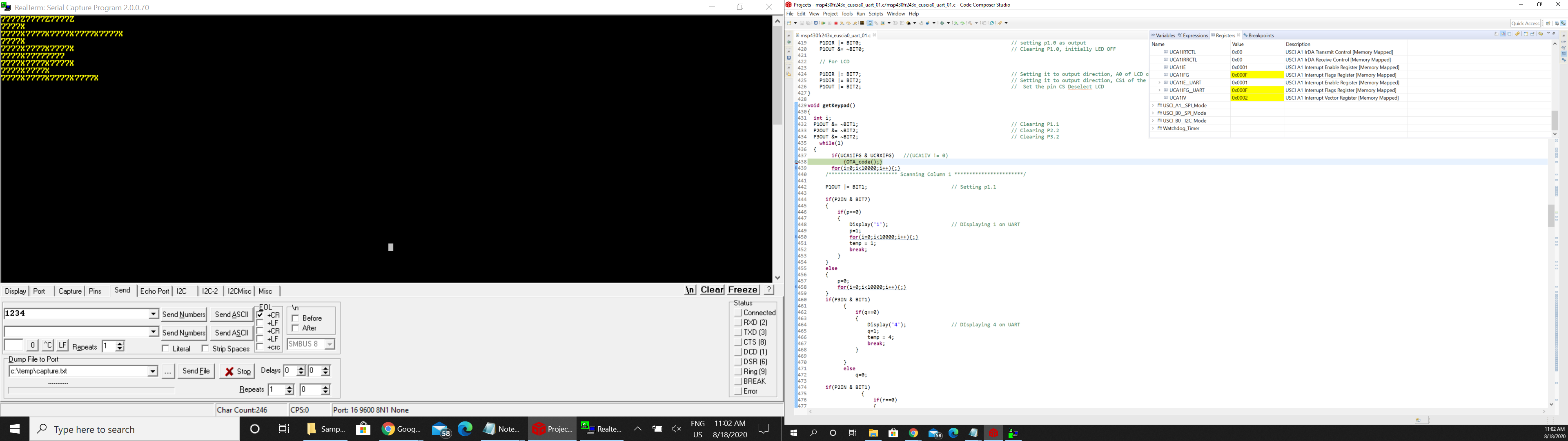
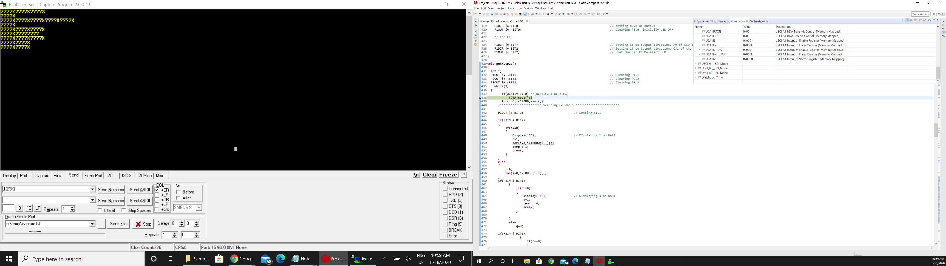
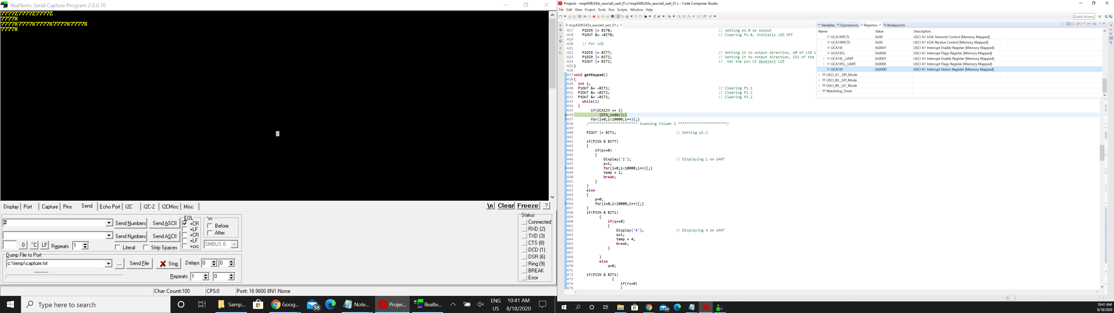
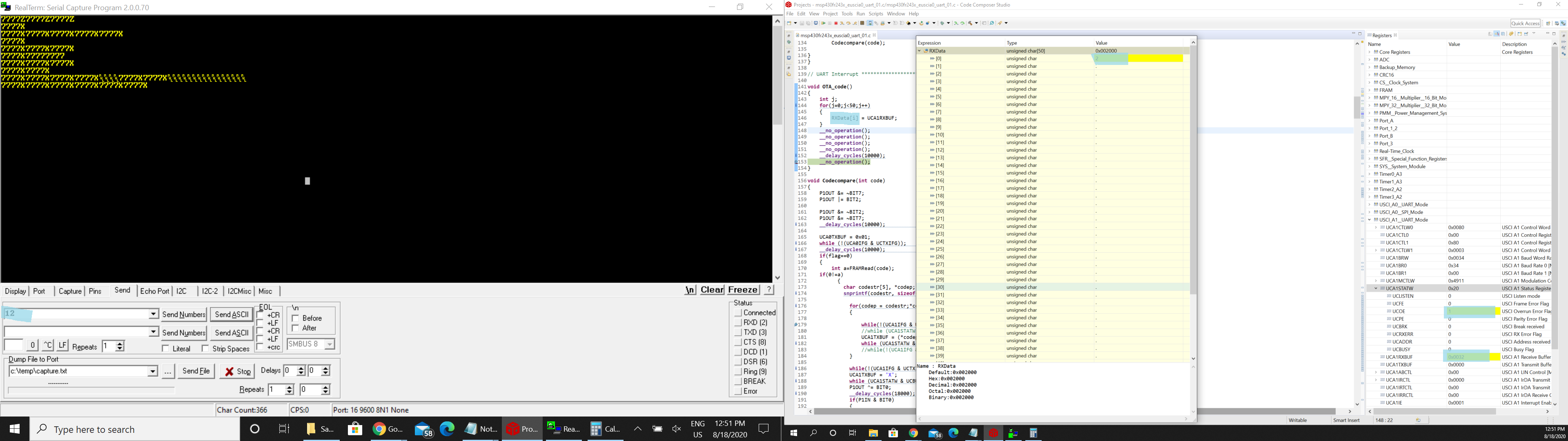
But for some reason, this never gets triggered. I have attached the complete code to this message. Please refer to lines 139-146 and 433-440. I have connected a scope and see that the Rx of micro is getting the data. Not sure why the interrupt isn't working.
Thank you
Varun R
//********************************* Headers****************************************
#include <msp430.h>
#include <math.h>
#include <stdio.h>
#include <stdlib.h>
#include <string.h>
#include <stdint.h>
#include <msp430fr2433.h>
//********************************** Global Variables *****************************
#define MCLK_FREQ_MHZ 8 // MCLK = 8MHz
volatile unsigned int p=0; volatile unsigned int q=0; volatile unsigned int r=0; volatile unsigned int s=0; volatile unsigned int t=0; volatile unsigned int u=0;
volatile unsigned int v=0; volatile unsigned int x=0; volatile unsigned int y=0; volatile unsigned int z=0; volatile unsigned int a=0; volatile unsigned int b=0;
int temp, code, counter=0;
char done[4] = {'D','O','N','E'};
unsigned char RXData;
unsigned char TXData;
unsigned int i, flag=0; // to avoid computing code when * or # are pressed
//********************************* Global Pointers ********************************
#define FRAM_counter_static 0x1800 // counter to always point at the start of the FRAM address
#define FRAM_TEST_START 0x1802 //
unsigned int *FRAM_write_ptr; // FRAM pointer to write
unsigned int *FRAM_read_ptr; // FRAM pointer to read
unsigned int *FRAM_counter_ptr; // counter pointer to read or write codes in to FRAM
//********************************** Function Prototype Declarations ***************
void Software_Trim(); // to get best possible clock (Helps with UART)
void Initialize(void); // to initialize LCD
void Display(char); // to display characters to LCD
void Init_GPIO(); // to initialize GPIO's
void Entercode(); // to enter the new code for the user after pressing *
void getKeypad(); // to get the key pressed on the keypad
void FRAMWrite(int); // to write the code into FRAM
int FRAMRead(int); // to read existing code form FRAM
void Init_FRAM(); // to delete all the codes from FRAM except Master code
void Codecompare(int); // to compare the code entered with codes in FRAM
void Dltcode(); // to delete a certain code
int index_read=0;
int index_write=0;
unsigned int codes[10];
int main(void)
{
WDTCTL = WDTPW | WDTHOLD; // Stop watchdog timer
PM5CTL0 &= ~LOCKLPM5; // Disable the GPIO power-on default high-impedance mode
FRAM_counter_ptr = (unsigned int *)FRAM_counter_static; // always pointed to 1800 location. This is where counter is located
// ************************************************************************ clock config // comment CLOCK config SPI works and UART doesn't ..... uncomment UART works SPI doesn't
__bis_SR_register(SCG0); // disable FLL
CSCTL3 |= SELREF__REFOCLK; // Set REFO as FLL reference source
CSCTL1 = DCOFTRIMEN|DCOFTRIM0|DCOFTRIM1|DCORSEL_3|DISMOD; // Enable frequency trim | DCOFTRIM=3, DCO Range = 8MHz | modulation disabled
CSCTL2 = FLLD_0 + 243; // DCODIV = 8MHz
__delay_cycles(3);
__bic_SR_register(SCG0); // enable FLL
Software_Trim(); // Software Trim to get the best DCOFTRIM value
CSCTL4 = SELMS__DCOCLKDIV | SELA__REFOCLK; // set default REFO(~32768Hz) as ACLK source, ACLK = 32768Hz
// *********************************************************************************************
P1SEL0 |= BIT4 | BIT5 | BIT6; // set 3-SPI pin as second function
UCA0CTLW0 |= UCSWRST; // **Put state machine in reset**
UCA0CTLW0 |= UCMST | UCSYNC | UCCKPL | UCMSB | UCMODE_0; // Master Mode | Sync mode | Inactive when CLK High | MSB first | 3-pin, 8-bit SPI master
UCA0CTLW0 |= UCSSEL__SMCLK; // SMCLK
UCA0BR0 = 0x08; // /2,fBitClock = fBRCLK/(UCBRx+1).
UCA0BR1 = 0;
UCA0MCTLW = 0; // No modulation
UCA0CTLW0 &= ~UCSWRST; // **Initialize USCI state machine**
//UCA0IE |= UCRXIE;
//****************************************************************************************************
P2SEL0 |= BIT5 | BIT6; // set 2-UART pin as second function
UCA1CTLW0 |= UCSWRST;
UCA1CTLW0 |= UCSSEL__SMCLK;
UCA1BR0 = 52; // 8000000/16/9600
UCA1BR1 = 0x00;
UCA1MCTLW = 0x4900 | UCOS16 | UCBRF_1;
UCA1STATW |= 0x0080;
UCA1CTLW0 &= ~UCSWRST;
UCA1IE |= UCRXIE; // Enable USCI_A0 RX interrupt
//__bis_SR_register(LPM0_bits|GIE); // Enter LPM3, interrupts enabled
__no_operation();
//**************************************************************************************************************
P1DIR &= ~BIT0; // Set P1.0 as input Manually excecute the code pin
Init_FRAM(); // Delete all the codes except Master code
//FRAMWrite(Master_Code); // Writing the Master code to the FRAM
//FRAMWrite(counter); // to keep track of FRAM memory location
Init_GPIO(); // Initialize GPIO's
Initialize();
//__enable_interrupt(); // enable all interrupts --> GIE = 1 (HIGH)
while(1)
{
P1OUT &= ~BIT2; // clear pin CS2 to select chip
P1OUT |= BIT7; // set A0 to enable write data
__delay_cycles(10000); // Delay before next transmission
Display('C'); Display('O'); Display('D'); Display('E'); Display(' '); Display('I'); Display('N'); Display('?');
P1OUT &= ~BIT2; // clear pin CS2 to select chip
P1OUT &= ~BIT7; // clear pin A0 to enter command mode
__delay_cycles(4000); // Delay before next transmission
UCA0TXBUF = 0xC0; // Setting Address register to Second line
while (!(UCA0IFG & UCTXIFG)); // USCI_A0 TX buffer ready?
__delay_cycles(1000); // Delay before next transmission
P1OUT &= ~BIT7; // clear pin A0 to enter command mode Default
P1OUT |= BIT2; // Set the pin CS, Deselecting Chip
int f=1000,j;
code=0;
for(i=0;i<4;i++)
{
getKeypad();
code = (code+(f*temp));
f = f/10;
}
Codecompare(code);
}
}
// UART Interrupt ***********************************************************
void OTA_code()
{
//while(!(UCA1IFG&UCTXIFG));
RXData = UCA1RXBUF;
__no_operation();
}
void Codecompare(int code)
{
P1OUT &= ~BIT7; // clear pin A0 to enter command mode Default
P1OUT |= BIT2; // Set the pin CS, Deselecting Chip
P1OUT &= ~BIT2; // clear pin CS2 to select chip
P1OUT &= ~BIT7; // clear pin A0 to enter command mode
__delay_cycles(10000); // Delay before next transmission
UCA0TXBUF = 0x01; // Clear Display
while (!(UCA0IFG & UCTXIFG)); // USCI_A0 TX buffer ready?
__delay_cycles(10000); // Delay before next transmission
if(flag==0) // no comparison when * or # are pressed
{
int a=FRAMRead(code);
if(0!=a)
{
char codestr[5], *codep;
snprintf(codestr, sizeof(codestr), "%d", code); // format as characters
for(codep = codestr;*codep != '\0';++codep) // send them one at a time
{
while(!(UCA1IFG & UCTXIFG));
//while (UCA1STATW & UCBUSY); // byte sent?
UCA1TXBUF = (*codep);
while (UCA1STATW & UCBUSY); // byte sent?
//while(!(UCA1IFG & UCTXIFG));
}
while(!(UCA1IFG & UCTXIFG));
UCA1TXBUF = 'Z'; // Sending end character
P1OUT ^= BIT0; // toogle p1.0
__delay_cycles(8000);
if(P1IN & BIT0) // is set say open
{
Display('O'); Display('N'); Display(' ');
}
else // if clear say close
{
Display('O'); Display('F'); Display('F'); Display(' ');
}
}
else // incorrect code entered
{
__delay_cycles(8000); // Delay before next transmission
Display('W'); Display('R'); Display('O'); Display('N'); Display('G');
P1OUT &= ~BIT2; // clear pin CS2 to select chip
P1OUT &= ~BIT7; // clear pin A0 to enter command mode
__delay_cycles(10000); // Delay before next transmission
UCA0TXBUF = 0xC0; // Setting Address register to Second line
while (!(UCA0IFG & UCTXIFG)); // USCI_A0 TX buffer ready?
__delay_cycles(8000); // Delay before next transmission
P1OUT &= ~BIT7; // clear pin A0 to enter command mode Default
P1OUT |= BIT2; // Set the pin CS, Deselecting Chip
}
}
else
flag=0;
}
void Entercode()
{
P1OUT &= ~BIT2; // clear pin CS2 to select chip
P1OUT &= ~BIT7; // clear pin A0 to enter command mode
__delay_cycles(4000); // Delay before next transmission
while (!(UCA0IFG & UCTXIFG)); // USCI_A0 TX buffer ready?
UCA0TXBUF = 0x01; // Clear Display
while (UCA0STATW & UCBUSY); // byte sent?
__delay_cycles(100); // Delay before next transmission
P1OUT |= BIT7; // set A0 to enable write data
__delay_cycles(12000); // Delay before next transmission
while (!(UCA0IFG & UCTXIFG)); // USCI_A0 TX buffer ready?
Display('N'); Display('E'); Display('W'); Display(' '); Display('C'); Display('O'); Display('D'); Display('E');
while (UCA0STATW & UCBUSY); // byte sent?
P1OUT &= ~BIT2; // clear pin CS2 to select chip
P1OUT &= ~BIT7; // clear pin A0 to enter command mode
__delay_cycles(4000); // Delay before next transmission
UCA0TXBUF = 0xC0; // Setting Address register to Second line
while (!(UCA0IFG & UCTXIFG)); // USCI_A0 TX buffer ready?
__delay_cycles(100); // Delay before next transmission
int f=1000;
for(i=0;i<4;i++)
{
getKeypad();
code = (code+(f*temp));
f = f/10;
}
int a=FRAMRead(code);
P1OUT |= BIT7; // set A0 to enable write data
__delay_cycles(12000); // Delay before next transmission
if(0==a) // No matching code found
{
FRAMWrite(code);
Display('D'); Display('O'); Display('N'); Display('E');
}
else if(0!=a) // code already exists
{
Display('T'); Display('A'); Display('K'); Display('E'); Display('N');
}
P1OUT &= ~BIT7; // clear pin A0 to enter command mode Default
P1OUT |= BIT2; // Set the pin CS, Deselecting Chip
}
void Dltcode()
{
P1OUT &= ~BIT2; // clear pin CS2 to select chip
P1OUT &= ~BIT7; // clear pin A0 to enter command mode
__delay_cycles(4000); // Delay before next transmission
UCA0TXBUF = 0x01; // Clear Display
while (!(UCA0IFG & UCTXIFG)); // USCI_A0 TX buffer ready?
__delay_cycles(100); // Delay before next transmission
P1OUT |= BIT7; // set A0 to enable write data
__delay_cycles(12000); // Delay before next transmission
Display('D'); Display('L'); Display('T'); Display(' '); Display('C'); Display('O'); Display('D'); Display('E');
P1OUT &= ~BIT2; // clear pin CS2 to select chip
P1OUT &= ~BIT7; // clear pin A0 to enter command mode
__delay_cycles(4000); // Delay before next transmission
UCA0TXBUF = 0xC0; // Setting Address register to Second line
while (!(UCA0IFG & UCTXIFG)); // USCI_A0 TX buffer ready?
__delay_cycles(100); // Delay before next transmission
int f=1000;
for(i=0;i<4;i++)
{
getKeypad();
code = (code+(f*temp));
f = f/10;
}
int check=1;
check = FRAMRead(code); // index where the dlt code is located, need to delete this location
counter = *FRAM_counter_ptr;
if(0!=check) // code found
{
FRAM_read_ptr = (unsigned int *)FRAM_TEST_START; // address to read 1802
FRAM_write_ptr = (unsigned int *)FRAM_TEST_START; // address to write inititially 0x1802
SYSCFG0 = FRWPPW | PFWP; // not protecting the data section so that we can write to the data section while the program section is protected
FRAM_read_ptr = FRAM_read_ptr + check; // Reading from the location after delete location
FRAM_write_ptr = FRAM_write_ptr + check - 1; // pointing it to write to delete location
for(;check <= counter;check++)
{
*FRAM_write_ptr = *FRAM_read_ptr; // copies data from next location to delete location
*FRAM_write_ptr++; // Next location
*FRAM_read_ptr++; // Next location
}
counter = *FRAM_counter_ptr;
counter--;
*FRAM_counter_ptr = counter;
SYSCFG0 = FRWPPW | PFWP | DFWP; // NOW WE ARE PROTECTING THE DATA SECTION AND THE PROGRAM SECTION
}
}
void FRAMWrite(int FRAM_Code)
{
FRAM_write_ptr = (unsigned int *)FRAM_TEST_START; // address to write inititially 0x1802
SYSCFG0 = FRWPPW | PFWP; // not protecting the data section so that we can write to the data section while the program section is protected
counter = *FRAM_counter_ptr;
FRAM_write_ptr = FRAM_write_ptr + counter;
*FRAM_write_ptr = FRAM_Code;
//*FRAM_write_ptr++;
counter++;
*FRAM_counter_ptr = counter;
SYSCFG0 = FRWPPW | PFWP | DFWP; // NOW WE ARE PROTECTING THE DATA SECTION AND THE PROGRAM SECTION
}
int FRAMRead(int FRAM_Code)
{
int j,temp=0;
FRAM_read_ptr = (unsigned int *)FRAM_TEST_START; // address to read 1802
if(FRAM_Code != 0)
{
for(j=1;j<10;j++)
{
if(FRAM_Code == *FRAM_read_ptr++) // comparing codes to FRAM
{ temp=j; break; } // 0 if there is a match
}
}
return(temp);
}
void Init_FRAM() // Factory reset FRAM
{
int i,temp = 0000; // avoid this code all the time
FRAM_write_ptr = (unsigned int *)0x1800; // address to write
SYSCFG0 = FRWPPW | PFWP; // not protecting the data section so that we can write to the data section while the program section is protected
for(i=0;i<12;i++) // 10 code limit
{
*FRAM_write_ptr = temp;
*FRAM_write_ptr++;
}
SYSCFG0 = FRWPPW | PFWP | DFWP; // Now we are protecting the data section and the program section
temp = 7777;
FRAMWrite(temp);
}
void Initialize()
{
UCA0IE |= UCTXIE; // Enable TX interrupt
P1OUT &= ~BIT2; // clear pin CS2 to select chip
P1OUT &= ~BIT7; // clear pin A0 to enter command mode
__delay_cycles(12000); // Delay before next transmission
UCA0TXBUF = 0x38; // Function Set
while (!(UCA0IFG & UCTXIFG)); // USCI_A0 TX buffer ready?
while (UCA0STATW & UCBUSY); // byte sent?
__delay_cycles(1000); // Delay before next transmission
UCA0TXBUF = 0x0F; // Display ON
while (!(UCA0IFG & UCTXIFG)); // USCI_A0 TX buffer ready?
while (UCA0STATW & UCBUSY); // byte sent?
__delay_cycles(1000); // Delay before next transmission
UCA0TXBUF = 0x01; // Clear Display
while (!(UCA0IFG & UCTXIFG)); // USCI_A0 TX buffer ready?
while (UCA0STATW & UCBUSY); // byte sent?
__delay_cycles(90000); // Delay before next transmission
UCA0TXBUF = 0x06; // Entry Mode Set
while (!(UCA0IFG & UCTXIFG)); // USCI_A0 TX buffer ready?
while (UCA0STATW & UCBUSY); // byte sent?
__delay_cycles(1000); // Delay before next transmission
P1OUT |= BIT2; // Set the pin CS unselect chip
P1OUT &= ~BIT7; // Clear pin dafault command mode
__delay_cycles(10000); // Delay before next transmission
//***************************************************************************************************************************************************
}
void Init_GPIO()
{
P1DIR = 0xFF; P2DIR = 0xFF; P3DIR = 0xFF;
P1REN = 0xFF; P2REN = 0xFF; P3REN = 0xFF;
P1OUT = 0x00; P2OUT = 0x00; P3OUT = 0x00;
P1DIR |= BIT1; // setting p1.1 as output
P1OUT &= ~BIT1; // Clearing P1.1
P2DIR |= BIT2; // setting p2.2 as output
P2OUT &= ~BIT2; // Clearing P2.2
P3DIR |= BIT2; // setting p3.2 as output
P3OUT &= ~BIT2; // Clearing P3.2
P2DIR &= ~BIT7; // Setting p2.7 as input
P3DIR &= ~BIT1; // Setting p3.1 as input
P2DIR &= ~BIT1; // Setting p2.1 as input
P2DIR &= ~BIT0; // Setting p2.0 as input
P1DIR |= BIT0; // setting p1.0 as output
P1OUT &= ~BIT0; // Clearing P1.0, initially LED OFF
// For LCD
P1DIR |= BIT7; // Setting it to output direction, A0 of LCD or RS resister Select
P1DIR |= BIT2; // Setting it to output direction, CS1 of the LCD, normally High, need to pull low before transferring data
P1OUT |= BIT2; // Set the pin CS Deselect LCD
}
void getKeypad()
{
int i;
P1OUT &= ~BIT1; // Clearing P1.1
P2OUT &= ~BIT2; // Clearing P2.2
P3OUT &= ~BIT2; // Clearing P3.2
while(1)
{
if(UCA1IV == 2)
{OTA_code();}
for(i=0;i<10000;i++){;}
/*********************** Scanning Column 1 ***********************/
P1OUT |= BIT1; // Setting p1.1
if(P2IN & BIT7)
{
if(p==0)
{
Display('1'); // DIsplaying 1 on UART
p=1;
for(i=0;i<10000;i++){;}
temp = 1;
break;
}
}
else
{
p=0;
for(i=0;i<10000;i++){;}
}
if(P3IN & BIT1)
{
if(q==0)
{
Display('4'); // DIsplaying 4 on UART
q=1;
temp = 4;
break;
}
}
else
q=0;
if(P2IN & BIT1)
{
if(r==0)
{
Display('7'); // DIsplaying 7 on UART
r=1;
temp = 7;
break;
}
}
else
r=0;
if(P2IN & BIT0)
{
if(s==0)
{
Display('*'); // DIsplaying * on UART
s=1;
//index_write++;
Entercode();
flag=1;
i=4;
break;
}
}
else
s=0;
P1OUT &= ~BIT1; // Clearing P1.1
for(i=0;i<10000;i++){;}
/*********************** Scanning Column 2 ***********************/
P2OUT |= BIT2; // Setting p2.2
if(P2IN & BIT7)
{
if(t==0)
{
Display('2'); // DIsplaying 2 on UART
for(i=0;i<10000;i++){;}
t=1;
temp = 2;
break;
}
}
else{
t=0;
for(i=0;i<10000;i++){;}
}
if(P3IN & BIT1)
{
if(u==0)
{
Display('5'); // DIsplaying 5 on UART
u=1;
temp = 5;
break;
}
}
else
u=0;
if(P2IN & BIT1)
{
if(v==0)
{
Display('8'); // DIsplaying 8 on UART
v=1;
temp = 8;
break;
}
}
else
v=0;
if(P2IN & BIT0)
{
if(x==0)
{
Display('0'); // DIsplaying 0 on UART
x=1;
temp = 0;
break;
}
}
else
x=0;
P2OUT &= ~BIT2; // Clearing P2.2
for(i=0;i<10000;i++){;}
/*********************** Scanning Column 3 ***********************/
P3OUT |= BIT2; // Setting p3.2
if(P2IN & BIT7)
{
if(y==0)
{
Display('3'); // DIsplaying 3 on UART
for(i=0;i<10000;i++){;}
y=1;
temp = 3;
break;
}
}
else{
y=0;
for(i=0;i<10000;i++){;}
}
if(P3IN & BIT1)
{
if(z==0)
{
Display('6'); // DIsplaying 6 on UART
z=1;
temp = 6;
break;
}
}
else
z=0;
if(P2IN & BIT1)
{
if(a==0)
{
Display('9'); // DIsplaying 9 on UART
a=1;
temp = 9;
break;
}
}
else
a=0;
if(P2IN & BIT0)
{
if(b==0)
{
Display('#'); // DIsplaying # on UART
b=1;
Dltcode();
flag=1;
i=4;
break;
}
}
else
b=0;
P3OUT &= ~BIT2; // Clearing P3.2
for(i=0;i<10000;i++){;}
}
}
void Display(char word)
{
P1OUT &= ~BIT2; // clear pin CS2 to select chip
P1OUT |= BIT7; // set A0 to enable write data
__delay_cycles(4000); // Delay before next transmission
switch(word)
{
case 'A':
UCA0TXBUF = 0x41; // Sending A to LCD
while (!(UCA0IFG & UCTXIFG)); // USCI_A0 TX buffer ready?
__delay_cycles(4000); // Delay before next transmission
break;
case 'B':
UCA0TXBUF = 0x42; // Sending B to LCD
while (!(UCA0IFG & UCTXIFG)); // USCI_A0 TX buffer ready?
__delay_cycles(4000); // Delay before next transmission
break;
case 'C':
UCA0TXBUF = 0x43; // Sending C to LCD
while (!(UCA0IFG & UCTXIFG)); // USCI_A0 TX buffer ready?
__delay_cycles(4000); // Delay before next transmission
break;
case 'D':
UCA0TXBUF = 0x44; // Sending D to LCD
while (!(UCA0IFG & UCTXIFG)); // USCI_A0 TX buffer ready?
__delay_cycles(4000); // Delay before next transmission
break;
case 'E':
UCA0TXBUF = 0x45; // Sending E to LCD
while (!(UCA0IFG & UCTXIFG)); // USCI_A0 TX buffer ready?
__delay_cycles(4000); // Delay before next transmission
break;
case 'F':
UCA0TXBUF = 0x46; // Sending F to LCD
while (!(UCA0IFG & UCTXIFG)); // USCI_A0 TX buffer ready?
__delay_cycles(4000); // Delay before next transmission
break;
case 'G':
UCA0TXBUF = 0x47; // Sending G to LCD
while (!(UCA0IFG & UCTXIFG)); // USCI_A0 TX buffer ready?
__delay_cycles(4000); // Delay before next transmission
break;
case 'H':
UCA0TXBUF = 0x48; // Sending H to LCD
while (!(UCA0IFG & UCTXIFG)); // USCI_A0 TX buffer ready?
__delay_cycles(4000); // Delay before next transmission
break;
case 'I':
UCA0TXBUF = 0x49; // Sending I to LCD
while (!(UCA0IFG & UCTXIFG)); // USCI_A0 TX buffer ready?
__delay_cycles(4000); // Delay before next transmission
break;
case 'J':
UCA0TXBUF = 0x4A; // Sending J to LCD
while (!(UCA0IFG & UCTXIFG)); // USCI_A0 TX buffer ready?
__delay_cycles(4000); // Delay before next transmission
break;
case 'K':
UCA0TXBUF = 0x4B; // Sending K to LCD
while (!(UCA0IFG & UCTXIFG)); // USCI_A0 TX buffer ready?
__delay_cycles(4000); // Delay before next transmission
break;
case 'L':
UCA0TXBUF = 0x4C; // Sending L to LCD
while (!(UCA0IFG & UCTXIFG)); // USCI_A0 TX buffer ready?
__delay_cycles(4000); // Delay before next transmission
break;
case 'M':
UCA0TXBUF = 0x4D; // Sending M to LCD
while (!(UCA0IFG & UCTXIFG)); // USCI_A0 TX buffer ready?
__delay_cycles(4000); // Delay before next transmission
break;
case 'N':
UCA0TXBUF = 0x4E; // Sending N to LCD
while (!(UCA0IFG & UCTXIFG)); // USCI_A0 TX buffer ready?
__delay_cycles(4000); // Delay before next transmission
break;
case 'O':
UCA0TXBUF = 0x4F; // Sending O to LCD
while (!(UCA0IFG & UCTXIFG)); // USCI_A0 TX buffer ready?
__delay_cycles(4000); // Delay before next transmission
break;
case 'P':
UCA0TXBUF = 0x50; // Sending P to LCD
while (!(UCA0IFG & UCTXIFG)); // USCI_A0 TX buffer ready?
__delay_cycles(4000); // Delay before next transmission
break;
case 'Q':
UCA0TXBUF = 0x51; // Sending Q to LCD
while (!(UCA0IFG & UCTXIFG)); // USCI_A0 TX buffer ready?
__delay_cycles(4000); // Delay before next transmission
break;
case 'R':
UCA0TXBUF = 0x52; // Sending R to LCD
while (!(UCA0IFG & UCTXIFG)); // USCI_A0 TX buffer ready?
__delay_cycles(4000); // Delay before next transmission
break;
case 'S':
UCA0TXBUF = 0x53; // Sending S to LCD
while (!(UCA0IFG & UCTXIFG)); // USCI_A0 TX buffer ready?
__delay_cycles(4000); // Delay before next transmission
break;
case 'T':
UCA0TXBUF = 0x54; // Sending T to LCD
while (!(UCA0IFG & UCTXIFG)); // USCI_A0 TX buffer ready?
__delay_cycles(4000); // Delay before next transmission
break;
case 'U':
UCA0TXBUF = 0x55; // Sending U to LCD
while (!(UCA0IFG & UCTXIFG)); // USCI_A0 TX buffer ready?
__delay_cycles(4000); // Delay before next transmission
break;
case 'V':
UCA0TXBUF = 0x56; // Sending V to LCD
while (!(UCA0IFG & UCTXIFG)); // USCI_A0 TX buffer ready?
__delay_cycles(4000); // Delay before next transmission
break;
case 'W':
UCA0TXBUF = 0x57; // Sending W to LCD
while (!(UCA0IFG & UCTXIFG)); // USCI_A0 TX buffer ready?
__delay_cycles(4000); // Delay before next transmission
break;
case 'X':
UCA0TXBUF = 0x58; // Sending X to LCD
while (!(UCA0IFG & UCTXIFG)); // USCI_A0 TX buffer ready?
__delay_cycles(4000); // Delay before next transmission
break;
case 'Y':
UCA0TXBUF = 0x59; // Sending Y to LCD
while (!(UCA0IFG & UCTXIFG)); // USCI_A0 TX buffer ready?
__delay_cycles(4000); // Delay before next transmission
break;
case 'Z':
UCA0TXBUF = 0x5A; // Sending Z to LCD
while (!(UCA0IFG & UCTXIFG)); // USCI_A0 TX buffer ready?
__delay_cycles(4000); // Delay before next transmission
break;
case '0':
UCA0TXBUF = 0x30; // Sending 0 to LCD
while (!(UCA0IFG & UCTXIFG)); // USCI_A0 TX buffer ready?
__delay_cycles(4000); // Delay before next transmission
break;
case '1':
UCA0TXBUF = 0x31; // Sending 1 to LCD
while (!(UCA0IFG & UCTXIFG)); // USCI_A0 TX buffer ready?
__delay_cycles(4000); // Delay before next transmission
break;
case '2':
UCA0TXBUF = 0x32; // Sending 2 to LCD
while (!(UCA0IFG & UCTXIFG)); // USCI_A0 TX buffer ready?
__delay_cycles(4000); // Delay before next transmission
break;
case '3':
UCA0TXBUF = 0x33; // Sending 3 to LCD
while (!(UCA0IFG & UCTXIFG)); // USCI_A0 TX buffer ready?
__delay_cycles(4000); // Delay before next transmission
break;
case '4':
UCA0TXBUF = 0x34; // Sending 4 to LCD
while (!(UCA0IFG & UCTXIFG)); // USCI_A0 TX buffer ready?
__delay_cycles(4000); // Delay before next transmission
break;
case '5':
UCA0TXBUF = 0x35; // Sending 5 to LCD
while (!(UCA0IFG & UCTXIFG)); // USCI_A0 TX buffer ready?
__delay_cycles(4000); // Delay before next transmission
break;
case '6':
UCA0TXBUF = 0x36; // Sending 6 to LCD
while (!(UCA0IFG & UCTXIFG)); // USCI_A0 TX buffer ready?
__delay_cycles(4000); // Delay before next transmission
break;
case '7':
UCA0TXBUF = 0x37; // Sending 7 to LCD
while (!(UCA0IFG & UCTXIFG)); // USCI_A0 TX buffer ready?
__delay_cycles(4000); // Delay before next transmission
break;
case '8':
UCA0TXBUF = 0x38; // Sending 8 to LCD
while (!(UCA0IFG & UCTXIFG)); // USCI_A0 TX buffer ready?
__delay_cycles(4000); // Delay before next transmission
break;
case '9':
UCA0TXBUF = 0x39; // Sending 9 to LCD
while (!(UCA0IFG & UCTXIFG)); // USCI_A0 TX buffer ready?
__delay_cycles(4000); // Delay before next transmission
break;
case '?':
UCA0TXBUF = 0x3F; // Sending ? to LCD
while (!(UCA0IFG & UCTXIFG)); // USCI_A0 TX buffer ready?
__delay_cycles(4000); // Delay before next transmission
break;
case '#':
UCA0TXBUF = 0x23; // Sending # to LCD
while (!(UCA0IFG & UCTXIFG)); // USCI_A0 TX buffer ready?
__delay_cycles(4000); // Delay before next transmission
break;
case '*':
UCA0TXBUF = 0x2A; // Sending * to LCD
while (!(UCA0IFG & UCTXIFG)); // USCI_A0 TX buffer ready?
__delay_cycles(4000); // Delay before next transmission
break;
case ' ':
UCA0TXBUF = 0x20; // Sending blank to LCD
while (!(UCA0IFG & UCTXIFG)); // USCI_A0 TX buffer ready?
__delay_cycles(4000); // Delay before next transmission
break;
case ';':
UCA0TXBUF = 0x3B; // Sending ; to LCD
while (!(UCA0IFG & UCTXIFG)); // USCI_A0 TX buffer ready?
__delay_cycles(4000); // Delay before next transmission
break;
}
P1OUT |= BIT2; // Set the pin CS, Deselecting Chip
P1OUT &= ~BIT7; // clear pin A0 to enter command mode Default
}
void Software_Trim()
{
unsigned int oldDcoTap = 0xffff;
unsigned int newDcoTap = 0xffff;
unsigned int newDcoDelta = 0xffff;
unsigned int bestDcoDelta = 0xffff;
unsigned int csCtl0Copy = 0;
unsigned int csCtl1Copy = 0;
unsigned int csCtl0Read = 0;
unsigned int csCtl1Read = 0;
unsigned int dcoFreqTrim = 3;
unsigned char endLoop = 0;
do
{
CSCTL0 = 0x100; // DCO Tap = 256
do
{
CSCTL7 &= ~DCOFFG; // Clear DCO fault flag
}while (CSCTL7 & DCOFFG); // Test DCO fault flag
__delay_cycles((unsigned int)3000 * MCLK_FREQ_MHZ);// Wait FLL lock status (FLLUNLOCK) to be stable
// Suggest to wait 24 cycles of divided FLL reference clock
while((CSCTL7 & (FLLUNLOCK0 | FLLUNLOCK1)) && ((CSCTL7 & DCOFFG) == 0));
csCtl0Read = CSCTL0; // Read CSCTL0
csCtl1Read = CSCTL1; // Read CSCTL1
oldDcoTap = newDcoTap; // Record DCOTAP value of last time
newDcoTap = csCtl0Read & 0x01ff; // Get DCOTAP value of this time
dcoFreqTrim = (csCtl1Read & 0x0070)>>4;// Get DCOFTRIM value
if(newDcoTap < 256) // DCOTAP < 256
{
newDcoDelta = 256 - newDcoTap; // Delta value between DCPTAP and 256
if((oldDcoTap != 0xffff) && (oldDcoTap >= 256)) // DCOTAP cross 256
endLoop = 1; // Stop while loop
else
{
dcoFreqTrim--;
CSCTL1 = (csCtl1Read & (~(DCOFTRIM0+DCOFTRIM1+DCOFTRIM2))) | (dcoFreqTrim<<4);
}
}
else // DCOTAP >= 256
{
newDcoDelta = newDcoTap - 256; // Delta value between DCPTAP and 256
if(oldDcoTap < 256) // DCOTAP cross 256
endLoop = 1; // Stop while loop
else
{
dcoFreqTrim++;
CSCTL1 = (csCtl1Read & (~(DCOFTRIM0+DCOFTRIM1+DCOFTRIM2))) | (dcoFreqTrim<<4);
}
}
if(newDcoDelta < bestDcoDelta) // Record DCOTAP closest to 256
{
csCtl0Copy = csCtl0Read;
csCtl1Copy = csCtl1Read;
bestDcoDelta = newDcoDelta;
}
}while(endLoop == 0); // Poll until endLoop == 1
CSCTL0 = csCtl0Copy; // Reload locked DCOTAP
CSCTL1 = csCtl1Copy; // Reload locked DCOFTRIM
while(CSCTL7 & (FLLUNLOCK0 | FLLUNLOCK1)); // Poll until FLL is locked
}