This thread has been locked.

If you have a related question, please click the "Ask a related question" button in the top right corner. The newly created question will be automatically linked to this question.

CCS/LAUNCHXL-CC26X2R1: LAUNCHXL-CC26X2R1

Part Number: LAUNCHXL-CC26X2R1
Other Parts Discussed in Thread: SYSCONFIG

Tool/software: Code Composer Studio

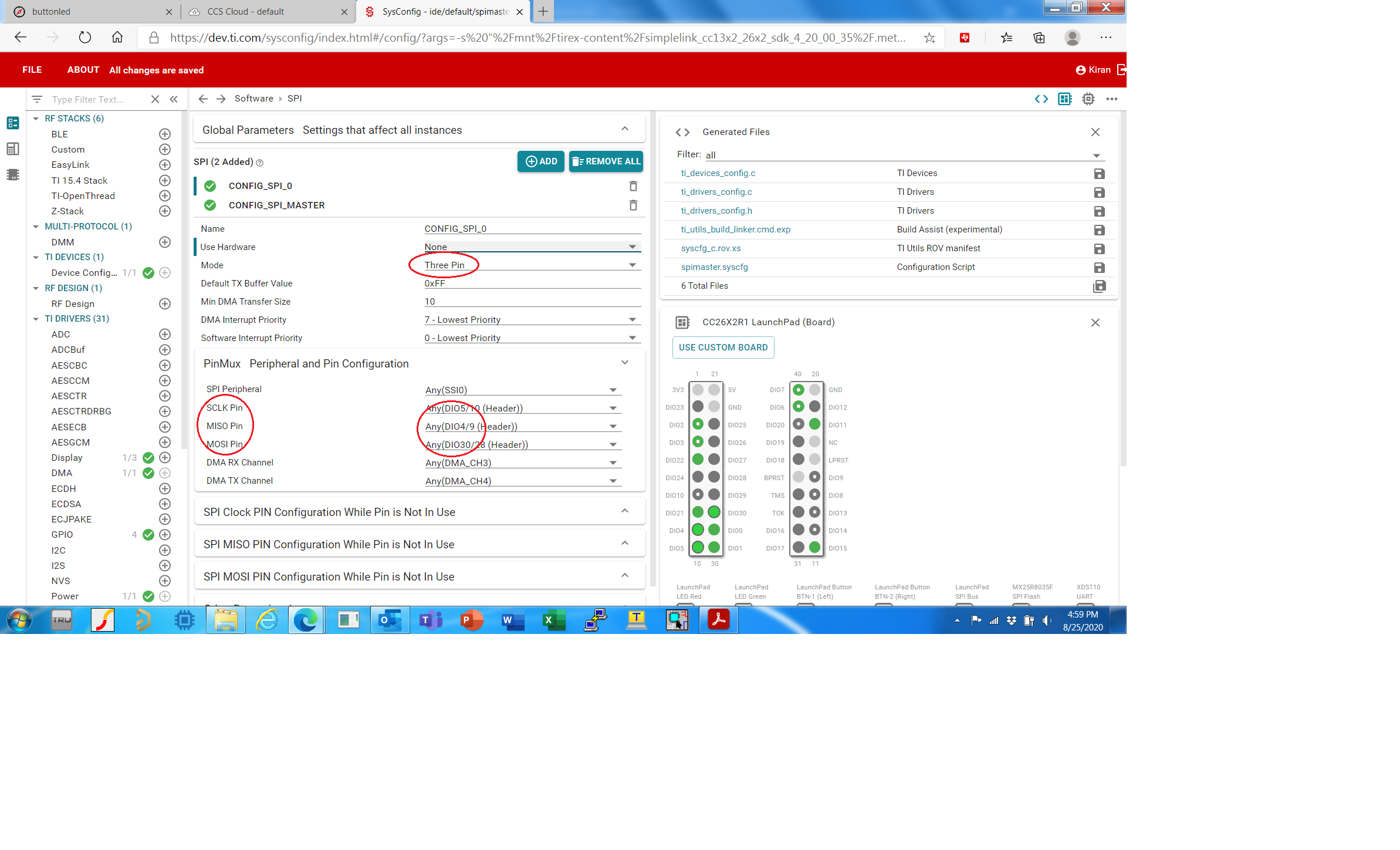
In Code Composer 3-wire SPI interface section, selected pins are SCLK, MISO and MOSI. Please see attached.

But in industry standard 3-wire SPI interface, pins are CS, SPC and SDI/O. Please see attached.

These are different from one in Code Composer. In Code composer there is no CS pin.

In industry standard 3-wire SPI interface MISO and MOSI are combined into a single pin SDI/O.

How do I fix this issue in Code Composer.

  • Hi Kiran,

    Please see this previous e2e post regarding 3-Wire SPI: https://e2e.ti.com/support/wireless-connectivity/sub-1-ghz/f/156/t/803998

    Unfortunately the 3-Wire half-duplex SPI mode isn't available in hardware on this device. The 3-wire mode here refers to the user controlling the CS line manually. You may be able to write your own driver or bit-bang a solution using the Sensor Controller on the device to achieve half-duplex 3-Wire SPI mode.

    Please see Chapter 22 of the CC13x2 CC26x2 TRM for available SPI modes: https://www.ti.com/lit/ug/swcu185d/swcu185d.pdf

    Regards,

    Daniel

  • Thanks, Daniel.

    I tried your suggestion of controlling CS line manually. But it didn't work.

    I will try again and see if I can make it work. At present I am using both the SPI buses and got two SPI devices (4-wire) to work on PCB. I have one device on each SPI bus.

    But I have 5 SPI devices (4-wire) and need to make them work. I want to have one SPI bus  0 for on board serial flash and 2nd SPI bus 1 for 4 sensors (4-wire SPI).

    So far only flash on SPI0 and one sensor is working on SPI1.

    Thanks

    Kiran

  • Kiran,

    What I meant is that in the SPI 3-Wire mode shown in SysConfig in your screenshot above is a SPI mode where CLK, MISO, and MOSI are controlled by the SPI peripheral and the CS/SS pin is controlled by the user manually in their code. Typically this would be a GPIO you configure and toggle high and low as needed.

    In the case of using multiple devices on a single SPI bus you would use 3-Wire mode and add GPIO(s) as needed to toggle CS high and low for each device on the bus.

    This is different from the 3-Wire half-duplex SPI mode your 2nd screenshot where MOSI and MISO are shared on a single line.

    I hope that helps to clarify.

    Regards,

    Daniel

  • Thanks, Daniel.

    Problem was with GPIO write instruction for CS to my sensor. Once that's fixed, it started working.

    I used RED LED (LED0 - DIO6) as chip select for my sensor. Then used LED0 OFF/ON instructions to enable and disable sensor.

    Then I used DIO11 with corrected write statements and problem was fixed.

    Thanks

    KM