This thread has been locked.

If you have a related question, please click the "Ask a related question" button in the top right corner. The newly created question will be automatically linked to this question.

CCS/OMAP-L138: Gel File Issues

Part Number: OMAP-L138

Tool/software: Code Composer Studio

Hi,

I'm trying to connect to the ARM9 inside the OMAP-L138 on the OMAP-L138LCDK dev board through an XDS100v3.

When the gel file from TI is launched prior to debug the below output is generated.

ARM9_0: Output:     Target Connected.
ARM9_0: Output:     ---------------------------------------------
ARM9_0: Output:     Memory Map Cleared.
ARM9_0: Output:     ---------------------------------------------
ARM9_0: Output:     Memory Map Setup Complete.
ARM9_0: Output:     ---------------------------------------------
ARM9_0: Output:     PSC Enable Complete.
ARM9_0: Output:     ---------------------------------------------
ARM9_0: GEL: Error while executing OnTargetConnect(): Target failed to write 0x01C11138
     at (*((unsigned int *) (0x01C11000+0x138))|=0x1) [OMAP-L138_LCDK.gel:16]
     at device_PLL0(0, 24, 1, 0, 1, 11, 5) [OMAP-L138_LCDK.gel:403]
     at Set_Core_300MHz() [OMAP-L138_LCDK.gel:468]
     at Core_300MHz_mDDR_150MHz() [OMAP-L138_LCDK.gel:245]
     at OnTargetConnect()

I found the below thread which talks about this same issue, but I don't think the probe I'm using falls into the same category.

https://e2e.ti.com/support/tools/ccs/f/81/p/786780/2912086#2912086

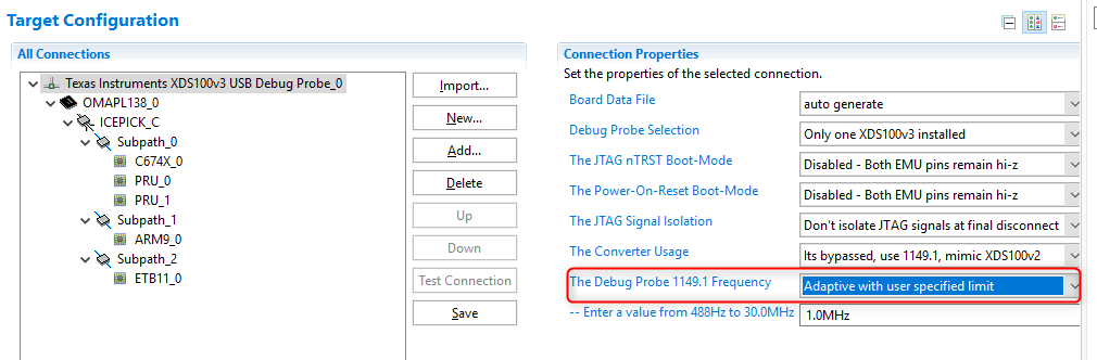
Should it only be the J-TAG settings then that's the issue?

Thanks,

Ben

  • Sorry,

    Also forgot to attached the J-TAG Integrity Scan which seems ok.

    [Start: Texas Instruments XDS100v3 USB Debug Probe_0]

    Execute the command:

    %ccs_base%/common/uscif/dbgjtag -f %boarddatafile% -rv -o -F inform,logfile=yes -S pathlength -S integrity

    [Result]


    -----[Print the board config pathname(s)]------------------------------------

    /root/.ti/ccs1010/0/0/BrdDat/testBoard.dat

    -----[Print the reset-command software log-file]-----------------------------

    This utility has selected a 100- or 510-class product.
    This utility will load the adapter 'libjioserdesusbv3.so'.
    The library build date was 'May  7 2020'.
    The library build time was '20:44:54'.
    The library package version is '9.2.0.00002'.
    The library component version is '35.35.0.0'.
    The controller does not use a programmable FPGA.
    The controller has a version number of '4' (0x00000004).
    The controller has an insertion length of '0' (0x00000000).
    This utility will attempt to reset the controller.
    This utility has successfully reset the controller.

    -----[Print the reset-command hardware log-file]-----------------------------

    The scan-path will be reset by toggling the JTAG TRST signal.
    The controller is the FTDI FT2232 with USB interface.
    The link from controller to target is direct (without cable).
    The software is configured for FTDI FT2232 features.
    The controller cannot monitor the value on the EMU[0] pin.
    The controller cannot monitor the value on the EMU[1] pin.
    The controller cannot control the timing on output pins.
    The controller cannot control the timing on input pins.
    The scan-path link-delay has been set to exactly '0' (0x0000).

    -----[The log-file for the JTAG TCLK output generated from the PLL]----------

      Test  Size   Coord      MHz    Flag  Result       Description
      ~~~~  ~~~~  ~~~~~~~  ~~~~~~~~  ~~~~  ~~~~~~~~~~~  ~~~~~~~~~~~~~~~~~~~
        1     64  - 01 00  500.0kHz   O    good value   measure path length
        2     64  + 00 00  1.000MHz  [O]   good value   apply explicit tclk

    There is no hardware for measuring the JTAG TCLK frequency.

    In the scan-path tests:
    The test length was 2048 bits.
    The JTAG IR length was 6 bits.
    The JTAG DR length was 1 bits.

    The IR/DR scan-path tests used 2 frequencies.
    The IR/DR scan-path tests used 500.0kHz as the initial frequency.
    The IR/DR scan-path tests used 1.000MHz as the highest frequency.
    The IR/DR scan-path tests used 1.000MHz as the final frequency.

    -----[Measure the source and frequency of the final JTAG TCLKR input]--------

    There is no hardware for measuring the JTAG TCLK frequency.

    -----[Perform the standard path-length test on the JTAG IR and DR]-----------

    This path-length test uses blocks of 64 32-bit words.

    The test for the JTAG IR instruction path-length succeeded.
    The JTAG IR instruction path-length is 6 bits.

    The test for the JTAG DR bypass path-length succeeded.
    The JTAG DR bypass path-length is 1 bits.

    -----[Perform the Integrity scan-test on the JTAG IR]------------------------

    This test will use blocks of 64 32-bit words.
    This test will be applied just once.

    Do a test using 0xFFFFFFFF.
    Scan tests: 1, skipped: 0, failed: 0
    Do a test using 0x00000000.
    Scan tests: 2, skipped: 0, failed: 0
    Do a test using 0xFE03E0E2.
    Scan tests: 3, skipped: 0, failed: 0
    Do a test using 0x01FC1F1D.
    Scan tests: 4, skipped: 0, failed: 0
    Do a test using 0x5533CCAA.
    Scan tests: 5, skipped: 0, failed: 0
    Do a test using 0xAACC3355.
    Scan tests: 6, skipped: 0, failed: 0
    All of the values were scanned correctly.

    The JTAG IR Integrity scan-test has succeeded.

    -----[Perform the Integrity scan-test on the JTAG DR]------------------------

    This test will use blocks of 64 32-bit words.
    This test will be applied just once.

    Do a test using 0xFFFFFFFF.
    Scan tests: 1, skipped: 0, failed: 0
    Do a test using 0x00000000.
    Scan tests: 2, skipped: 0, failed: 0
    Do a test using 0xFE03E0E2.
    Scan tests: 3, skipped: 0, failed: 0
    Do a test using 0x01FC1F1D.
    Scan tests: 4, skipped: 0, failed: 0
    Do a test using 0x5533CCAA.
    Scan tests: 5, skipped: 0, failed: 0
    Do a test using 0xAACC3355.
    Scan tests: 6, skipped: 0, failed: 0
    All of the values were scanned correctly.

    The JTAG DR Integrity scan-test has succeeded.

    [End: Texas Instruments XDS100v3 USB Debug Probe_0]

  • Further information after reading some other posts on the form here:

    The OMAP-L138 is configured to boot from SD card, SW 1 - 3 = OFF and SW4 = ON

    The SD card is removed from the device.

    Code Composer Studio Version: 10.1.0.00010

  • It could be an adaptive clocking issue:. What vendor is your debug probe from? Olimex?

    https://e2e.ti.com/support/tools/ccs/f/81/p/447241/1628422#1628422

  • Hi Ki,

    I'm not too sure at this point where we got the debugger from.

    The silkscreen on the debugger says Spectrum Digital Incorporated.

    Ben

  • Hi Ki,

    I read some of the post you put in the reply.

    Pin 9 is populated on my debugger connector and cables.

    Pin 6 is not soldered to the board on any of the connectors though.

    Ben

  • Benjamin Michaud said:
    The silkscreen on the debugger says Spectrum Digital Incorporated.

    I assume then that you are using a Spectrum Digital XDS100v3 probe.

    Can you check your target configuration settings and see if "Adaptive with user specified limit" is selected?

    Thanks

    ki

  • Benjamin Michaud said:
    The OMAP-L138 is configured to boot from SD card, SW 1 - 3 = OFF and SW4 = ON

    Based on this link:

    http://software-dl.ti.com/processor-sdk-rtos/esd/docs/latest/rtos/index_how_to_guides.html#id77

    "Set the SW1 DIP switches to UART boot mode"

    Have you tried this?

  • Hi Ki,

    My setting for The Debug Probe 1149.1 Frequency was set to "Fixed Default at 1.0 MHz".

    Once I set it to "Adaptive with user specified limit" the debug probe successfully set the gel file memory register values.

    The code can now load and execute.

    Thanks,

    Ben