This thread has been locked.

If you have a related question, please click the "Ask a related question" button in the top right corner. The newly created question will be automatically linked to this question.

CCS/TMS320F28379D: TMS320F28379D LaunchPadXL interface with SD via SPI

Part Number: TMS320F28379D

Tool/software: Code Composer Studio

Hi Everyone,

I am use TMS320F28379D LaunchPadXL board . I want to store that data on SD card module . So, right now. I have gone through the SD card interfacing example available on CCS in sd_card.c,mmc_F2837x.c,ff.c 

and this is my main code and Power_on setup mux-pin.I already change every SpicRegs to SpiaRegs  in mmc_F2837x.c.Next I am try to use f_mount,f_open,f_write,f_close but nothing happen.Did i do something wrong? Can anyone please suggest me.I am new this is my first developkit.

Thank

int
main(void)
{
    int nStatus;
    FIL file;
    WORD btw = 5;
    FRESULT fresult;
    WORD bw;
    char buff[] = {'t','e','s','t','\n'};

    //
    // Initialize System Control
    //
    InitSysCtrl();

#ifdef _FLASH
//
// Copy time critical code and Flash setup code to RAM
// This includes the following functions:  InitFlash();
// The  RamfuncsLoadStart, RamfuncsLoadSize, and RamfuncsRunStart
// symbols are created by the linker. Refer to the device .cmd file.
//
    memcpy(&RamfuncsRunStart, &RamfuncsLoadStart, (size_t)&RamfuncsLoadSize);

//
// Call Flash Initialization to setup flash waitstates
// This function must reside in RAM
//
    InitFlash();
#endif

    //
    // Initialize interrupt controller and vector table
    //
    InitPieCtrl();
    InitPieVectTable();

    //
    // Set the system tick to fire 100 times per second.
    //
    SysTickInit();
    SysTickPeriodSet(SysCtlClockGet(SYSTEM_CLOCK_SPEED) / 100);
    SysTickIntRegister(SysTickHandler);
    SysTickIntEnable();
    SysTickEnable();

    //
    // Enable Interrupts
    //
    IntMasterEnable();


    //SPI-A Initial
    power_on();

    //FatFs
    fresult = f_mount(0, &g_sFatFs);
        if(fresult != FR_OK)
        {
            return(fresult);
        }

        fresult = f_open(&file, "Test.txt", FA_CREATE_NEW);
        if(fresult != FR_OK)
        {
            return(fresult);
        }

        fresult = f_write(&file, buff, btw, &bw);
        if(fresult != FR_OK)
        {
            return(fresult);
        }

        fresult = f_close(&file);
        if(fresult != FR_OK)
        {
            return(fresult);
        }


}

Power_on setup pin 

void power_on (void)    //EDITED
{
    /*
     * This doesn't really turn the power on, but initializes the
     * SPI port and pins needed to talk to the SD card.
     */
    EALLOW;
    /* Enable the peripherals used to drive the SDC on SPI */
    CpuSysRegs.PCLKCR8.bit.SPI_A = 1;

    /*
     * Configure the appropriate pins to be SPI instead of GPIO. The CS
     * signal is directly driven to ensure that we can hold it low through a
     * complete transaction with the SD card.
     */


    //Unlock the SD-Card SPI GPIOs
    GpioCtrlRegs.GPBLOCK.bit.GPIO58 = 0;
    GpioCtrlRegs.GPBLOCK.bit.GPIO59 = 0;
    GpioCtrlRegs.GPBLOCK.bit.GPIO60 = 0;
    GpioCtrlRegs.GPBLOCK.bit.GPIO61 = 0;

    //Set up  MUX & DIR
    GpioCtrlRegs.GPBMUX2.bit.GPIO61 = 0;    //Leave as GPIO for manual CS control

    GpioCtrlRegs.GPBGMUX2.bit.GPIO58 = 15;
    GpioCtrlRegs.GPBGMUX2.bit.GPIO59 = 15;
    GpioCtrlRegs.GPBGMUX2.bit.GPIO60 = 15;
    GpioCtrlRegs.GPBGMUX2.bit.GPIO61 = 15;

    GpioCtrlRegs.GPBMUX2.bit.GPIO58 = 15;
    GpioCtrlRegs.GPBMUX2.bit.GPIO59 = 15;
    GpioCtrlRegs.GPBMUX2.bit.GPIO60 = 15;
    GpioCtrlRegs.GPBMUX2.bit.GPIO61 = 15;

    GpioCtrlRegs.GPBDIR.bit.GPIO61 = 1;

    //Set up GPIO Pull-up disables/enables
    GpioCtrlRegs.GPBPUD.bit.GPIO58 = 0;    //Needs to be normally pulled high
    GpioCtrlRegs.GPBPUD.bit.GPIO59 = 0;    //Needs to be normally pulled high
    GpioCtrlRegs.GPBPUD.bit.GPIO60 = 0;
    GpioCtrlRegs.GPBPUD.bit.GPIO61 = 0;

    //Set up GPIOs in asynch mode
    GpioCtrlRegs.GPBQSEL2.bit.GPIO58 = 3; // Asynch input
    GpioCtrlRegs.GPBQSEL2.bit.GPIO59 = 3;
    GpioCtrlRegs.GPBQSEL2.bit.GPIO60 = 3;
    GpioCtrlRegs.GPBQSEL2.bit.GPIO61 = 3;

    //Configure GPIOs for CPU1
    GpioCtrlRegs.GPBCSEL4.bit.GPIO58 = 0;
    GpioCtrlRegs.GPBCSEL4.bit.GPIO59 = 0;
    GpioCtrlRegs.GPBCSEL4.bit.GPIO60 = 0;
    GpioCtrlRegs.GPBCSEL4.bit.GPIO61 = 0;

    //Lock the SD-Card SPI GPIOs
    GpioCtrlRegs.GPBLOCK.bit.GPIO58 = 1;
    GpioCtrlRegs.GPBLOCK.bit.GPIO59 = 1;
    GpioCtrlRegs.GPBLOCK.bit.GPIO60 = 1;
    GpioCtrlRegs.GPBLOCK.bit.GPIO61 = 1;
    EDIS;


    /* Deassert the *** chip selects for both the SD card and serial flash */
    DESELECT();

    /* Configure the SPI C port */
    SpiaRegs.SPICCR.bit.SPISWRESET = 0;         //Set reset bit low
    SpiaRegs.SPICTL.bit.CLK_PHASE = 0;
    SpiaRegs.SPICCR.bit.CLKPOLARITY = 1;
    SpiaRegs.SPICTL.bit.MASTER_SLAVE = 1;       //Master mode
    SpiaRegs.SPIBRR.all = 63;                       //update value to proper setting for correct bitrate ( current: ~500kHz)
    SpiaRegs.SPICCR.bit.SPICHAR = 0x7;          //Set char length to 8 bits
    SpiaRegs.SPICTL.bit.TALK = 1;
    SpiaRegs.SPICCR.bit.SPISWRESET = 1;         //Release SPI from reset
    SpiaRegs.SPIPRI.bit.FREE = 1;
    SpiaRegs.SPIPRI.bit.SOFT = 1;

    /* Set DI and CS high and apply more than 74 pulses to SCLK for the card */
    /* to be able to accept a native command. */
    //send_initial_clock_train();

    //DELAY_US(50);

    PowerFlag = 1;
}

https://www.ti.com/tool/LAUNCHXL-F28379D  Developkit

https://www.amazon.com/Module-Storage-Adapter-Interface-Arduino/dp/B07PFDFPPC/ref=sr_1_13?dchild=1&keywords=arduino+sd+card+module&qid=1599798912&sr=8-13 

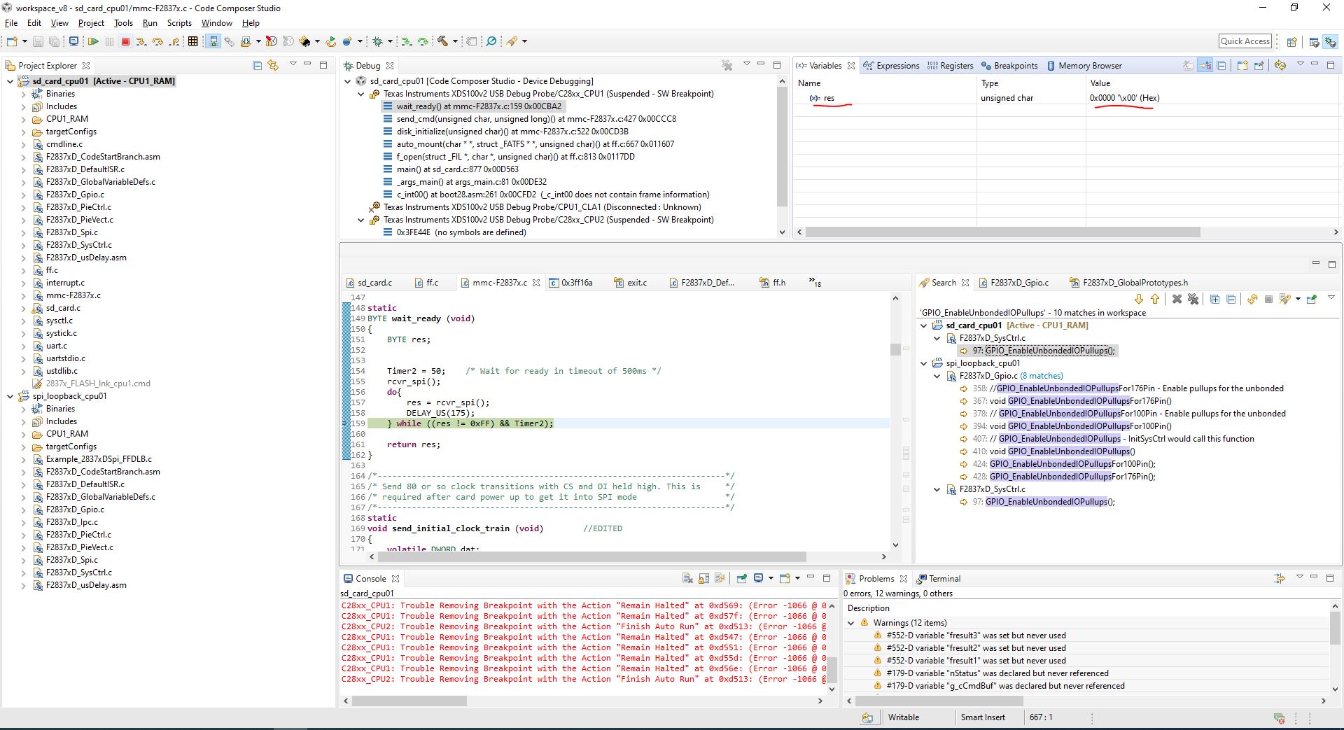
  • I found fresult return at f_open it's return  FR_NOT_READY. Then is use step into this function  f_open -> auto_mount -> disk_initialize -> send_cmd -> wait_ready

    it's always infinity loop because it always return 0x0000 not 0x00FF

    in additional cmd send correctly ( cmd = 0x0040)

  • Hello,  This has been assigned to one of C2000's engineers familiar with this area.  They are out of the office until Tuesday so you should hear back then.  

    We don't have any ready-out-of-the-box examples, but I found some related posts that may help.

    https://e2e.ti.com/support/microcontrollers/c2000/f/171/t/837159?CCS-LAUNCHXL-F28379D-how-to-use-SD-card-in-SPI-mode-

    https://e2e.ti.com/support/microcontrollers/c2000/f/171/t/870560?CCS-LAUNCHXL-F280049C-Micro-SD-Card-interfacing-with-F280049C

    Regards

    Lori

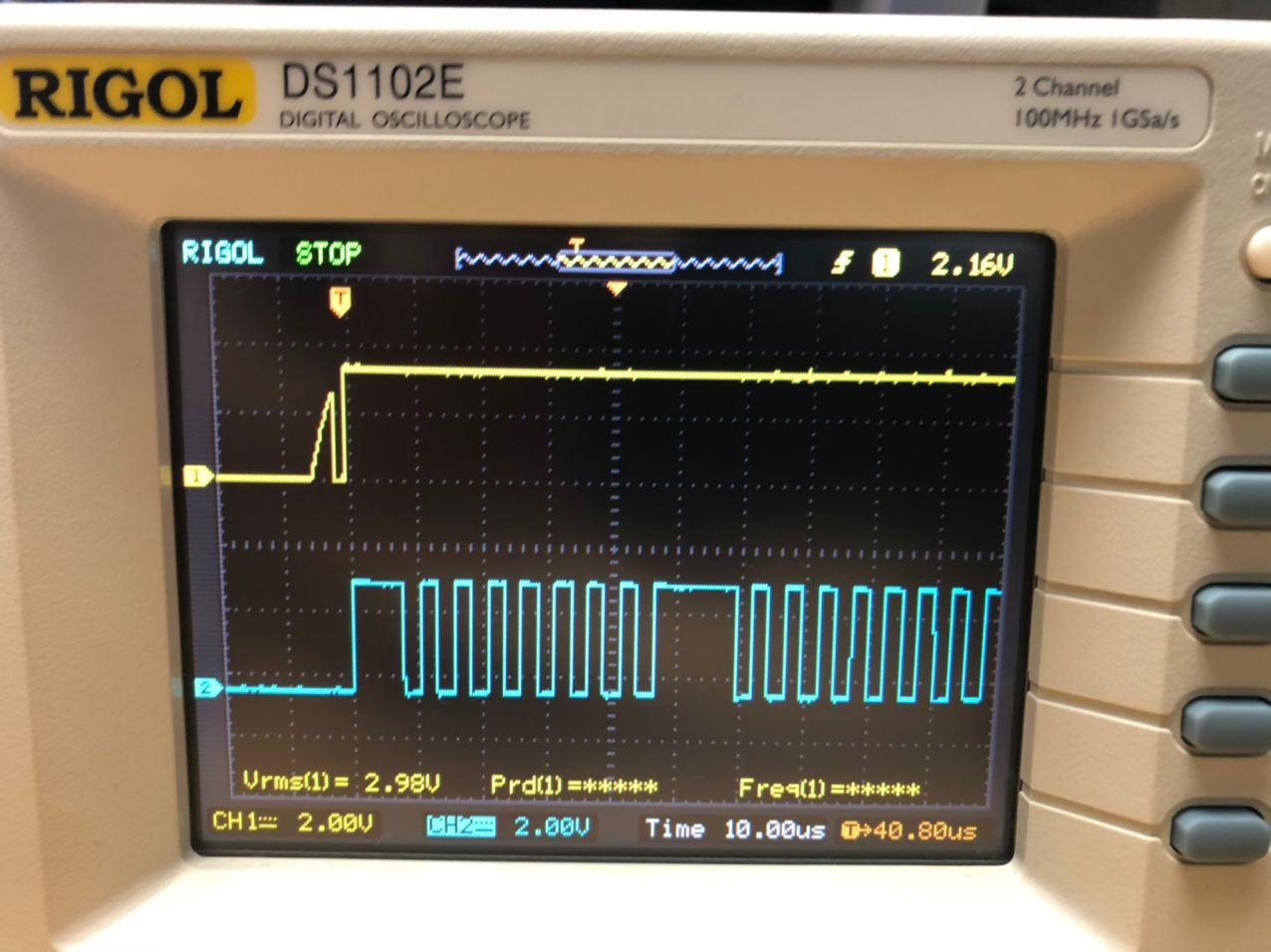
  • Do you have access to a logic analyzer or oscilloscope you could use to make sure the signals look okay?

    Is your chip select working? In the code you shared above, it looks like you set GPIO61 to a GPIO but then set it back to the hardware SPI CS--you need to keep it a GPIO for this code.

    Whitney

  • The signals i'll reply for you within tomorrow but I don't understand what do you mean "set GPIO61 to a GPIO but then set it back to the hardware SPI CS" Which line It's set back to GPIO? I

    I use a original code but it set SPI-C so I need to change to SPI-A and I change GPIO122,123,124,125 -> GPIO58,59,60,61.

    I use GPIO58(Pin 14 connect to MISO )

    GPIO59(Pin 15 connect to MOSI)

    GPIO60(Pin 7 connect to CLK)

    GPIO61(Pin 19 connect to CS)

    all GPIO set mux postion at 15

    reference from enc.sprs880m.pdfsprui77c.pdf

  • Here is my signals CH1 MOSI, CH2 CLK but at MISO nothing response

  • This is my SD card can I use for this project? 

  • The SD card code uses a software controlled chip select instead of the hardware one, so GPIO61 needs to be configured as a GPIO instead of an SPI CS pin. This means the GPBGMUX2 and GPBMUX2 registers should be configured to 0 for GPIO61. Also make sure you've updated the SELECT and DESELECT functions to use GPIO61.

    Whitney

  • Okay. Today I back to basic.I have F2837x ControlCard then I setting default config (SPI-C and use GPIO 122-125). "I can write file" but when I use a same code and use F2837x LaunchXL (PIN 18,17,13,12 [SPI-C]) connect with SD Card module. FR_result = FR_NOT_READY. This is my code updating.

    1.main()

    int main(void)
    {
        Uint16 sdata;  // send data
          Uint16 rdata;  // received data
          int nStatus;
           FIL file;
           FRESULT fresult;
           char buff[10];
           int i;
           BYTE diskResult;
    
    
        //
        // Set the clocking to run from the PLL at 50MHz
        //
        SysCtlClockSet(SYSCTL_OSCSRC_OSC2 | SYSCTL_PLL_ENABLE | SYSCTL_IMULT(10) |
                       SYSCTL_SYSDIV(2));
        SysCtlAuxClockSet(SYSCTL_OSCSRC_OSC2 | SYSCTL_PLL_ENABLE |
                          SYSCTL_IMULT(12) | SYSCTL_SYSDIV(2));        //60 MHz
    
    #ifdef _FLASH
    //
    // Copy time critical code and Flash setup code to RAM
    // This includes the following functions:  InitFlash();
    // The  RamfuncsLoadStart, RamfuncsLoadSize, and RamfuncsRunStart
    // symbols are created by the linker. Refer to the device .cmd file.
    //
        memcpy(&RamfuncsRunStart, &RamfuncsLoadStart, (size_t)&RamfuncsLoadSize);
    
    //
    // Call Flash Initialization to setup flash waitstates
    // This function must reside in RAM
    //
        InitFlash();
    #endif
    
        //
        // Initialize interrupt controller and vector table
        //
        InitPieCtrl();
        InitPieVectTable();
    
        //
        // Set the system tick to fire 100 times per second.
        //
        SysTickInit();
        SysTickPeriodSet(SysCtlClockGet(SYSTEM_CLOCK_SPEED) / 100);
        SysTickIntRegister(SysTickHandler);
        SysTickIntEnable();
        SysTickEnable();
    
        //
        // Enable Interrupts
        //
        IntMasterEnable();
    
    ////       //////////-------------------------InitialV2--------------------/////////////////
    //       //
    //       // Step 1. Initialize System Control:
    //       // PLL, WatchDog, enable Peripheral Clocks
    //       // This example function is found in the F2837xD_SysCtrl.c file.
    //       //
    //          InitSysCtrl();
    //
    //       //
    //       // Step 3. Clear all interrupts:
    //       //
    //          DINT;
    //
    //       //
    //       // Initialize PIE control registers to their default state.
    //       // The default state is all PIE __interrupts disabled and flags
    //       // are cleared.
    //       // This function is found in the F2837xD_PieCtrl.c file.
    //       //
    //          InitPieCtrl();
    //
    //       //
    //       // Disable CPU __interrupts and clear all CPU __interrupt flags:
    //       //
    //          IER = 0x0000;
    //          IFR = 0x0000;
    //
    //       //
    //       // Initialize the PIE vector table with pointers to the shell Interrupt
    //       // Service Routines (ISR).
    //       // This will populate the entire table, even if the __interrupt
    //       // is not used in this example.  This is useful for debug purposes.
    //       // The shell ISR routines are found in F2837xD_DefaultIsr.c.
    //       // This function is found in F2837xD_PieVect.c.
    //       //
    //          InitPieVectTable();


        fresult = f_mount(0, &g_sFatFs);
    
           {
               fresult =  f_open(&file, "0:/Test4.txt", FA_CREATE_NEW);
               f_close(&file);
               fresult =  f_open(&file, "0:/Test4.txt", FA_WRITE);
               if(fresult != FR_OK)
               {
                   return(1);
               }
               buff[0]='1';
               buff[1]='2';
               buff[2]='3';
               buff[3]='4';
               buff[4]='5';
               buff[5]='6';
               buff[6]='7';
               buff[7]='8';
               buff[8]='9';
               buff[9]='0';
               fresult = f_write (&file, buff, 10, (UINT *)&nStatus);
    
               if(fresult != FR_OK)
               {
                   //return(1);
               }
       //        fresult = f_sync (&file);
    
               f_sync(&file);
               f_close(&file);
           }
    

    2.power_on();

     static
    void power_on (void)	//EDITED
    {
    /*
           * This doesn't really turn the power on, but initializes the
           * SPI port and pins needed to talk to the SD card.
           */
          EALLOW;
          /* Enable the peripherals used to drive the SDC on SPI */
          CpuSysRegs.PCLKCR8.bit.SPI_C = 1;
    
          /*
           * Configure the appropriate pins to be SPI instead of GPIO. The CS
           * signal is directly driven to ensure that we can hold it low through a
           * complete transaction with the SD card.
           */
    
    
          //Unlock the SD-Card SPI GPIOs
          GpioCtrlRegs.GPDLOCK.bit.GPIO122 = 0;
          GpioCtrlRegs.GPDLOCK.bit.GPIO123 = 0;
          GpioCtrlRegs.GPDLOCK.bit.GPIO124 = 0;
          GpioCtrlRegs.GPDLOCK.bit.GPIO125 = 0;
    
          //Set up  MUX & DIR
          GpioCtrlRegs.GPDMUX2.bit.GPIO125 = 0;   //Leave as GPIO for manual CS control
    
          GpioCtrlRegs.GPDGMUX2.bit.GPIO122 = 1;
          GpioCtrlRegs.GPDGMUX2.bit.GPIO123 = 1;
          GpioCtrlRegs.GPDGMUX2.bit.GPIO124 = 1;
    
          GpioCtrlRegs.GPDMUX2.bit.GPIO122 = 2;
          GpioCtrlRegs.GPDMUX2.bit.GPIO123 = 2;
          GpioCtrlRegs.GPDMUX2.bit.GPIO124 = 2;
    
          GpioCtrlRegs.GPDDIR.bit.GPIO125 = 1;


          //Set up GPIO Pull-up disables/enables
          GpioCtrlRegs.GPDPUD.bit.GPIO122 = 0;    //Needs to be normally pulled high
          GpioCtrlRegs.GPDPUD.bit.GPIO123 = 0;    //Needs to be normally pulled high
          GpioCtrlRegs.GPDPUD.bit.GPIO124 = 1;
          GpioCtrlRegs.GPDPUD.bit.GPIO125 = 1;
    
          //Set up GPIOs in asynch mode
          GpioCtrlRegs.GPDQSEL2.bit.GPIO122 = 3; // Asynch input
          GpioCtrlRegs.GPDQSEL2.bit.GPIO123 = 3;
          GpioCtrlRegs.GPDQSEL2.bit.GPIO124 = 3;
          GpioCtrlRegs.GPDQSEL2.bit.GPIO125 = 3;
    
          //Configure GPIOs for CPU1
          GpioCtrlRegs.GPDCSEL4.bit.GPIO122 = 0;
          GpioCtrlRegs.GPDCSEL4.bit.GPIO123 = 0;
          GpioCtrlRegs.GPDCSEL4.bit.GPIO124 = 0;
          GpioCtrlRegs.GPDCSEL4.bit.GPIO125 = 0;
    
          //Lock the SD-Card SPI GPIOs
          GpioCtrlRegs.GPDLOCK.bit.GPIO122 = 1;
          GpioCtrlRegs.GPDLOCK.bit.GPIO123 = 1;
          GpioCtrlRegs.GPDLOCK.bit.GPIO124 = 1;
          GpioCtrlRegs.GPDLOCK.bit.GPIO125 = 1;
          EDIS;
    
    
          /* Deassert the *** chip selects for both the SD card and serial flash */
          DESELECT();
    
          /* Configure the SPI C port */
          SpicRegs.SPICCR.bit.SPISWRESET = 0;         //Set reset bit low
          SpicRegs.SPICTL.bit.CLK_PHASE = 0;
          SpicRegs.SPICCR.bit.CLKPOLARITY = 1;
          SpicRegs.SPICTL.bit.MASTER_SLAVE = 1;       //Master mode
          SpicRegs.SPIBRR.all = 63;                       //update value to proper setting for correct bitrate ( current: ~500kHz)
          SpicRegs.SPICCR.bit.SPICHAR = 0x7;          //Set char length to 8 bits
          SpicRegs.SPICTL.bit.TALK = 1;
          SpicRegs.SPICCR.bit.SPISWRESET = 1;         //Release SPI from reset
          SpicRegs.SPIPRI.bit.FREE = 1;
          SpicRegs.SPIPRI.bit.SOFT = 1;
    
          /* Set DI and CS high and apply more than 74 pulses to SCLK for the card */
          /* to be able to accept a native command. */
          //send_initial_clock_train();
    
          //DELAY_US(50);
    
          PowerFlag = 1;
    }

  • So the controlCARD code worked? Good to know that you SD card is working and compatible with this code. Did you determine whether or not the chip select was working correctly in the LaunchPad version of the project?

    Whitney

  • I'm not sure but I select from this.

  • Sorry, I meant the SPI protocol chip select (CS) pin--GPIO61. If you look at it on the scope does it seem to be working correctly?

    Whitney

  • Dear Whitney

    Now I working on another project but I think a caused come SD module (https://e2e.ti.com/support/microcontrollers/c2000/f/171/t/708133?TMS320F2812-SD-card-Interface). I'll order new module and try it later If it work I'll update here.