Part Number: TCI6486CSL
Tool/software: Code Composer Studio
I am facing issue when I am trying to connect JTAG debugger using Blackhawk USB-510(BH-USB-510) emulator which is needed by our hardware(TCI6486) on CCSv8.3
We are using windows 10, 64bit environment.
When I am trying to connect the target I got below error:
"Error connecting to the target:
(Error -1265 @ 0x0)
Device ID is not recognized or is not supported by driver. Confirm device and debug probe configuration is correct, or update device driver.
(Emulation package 6.0.83.0)"
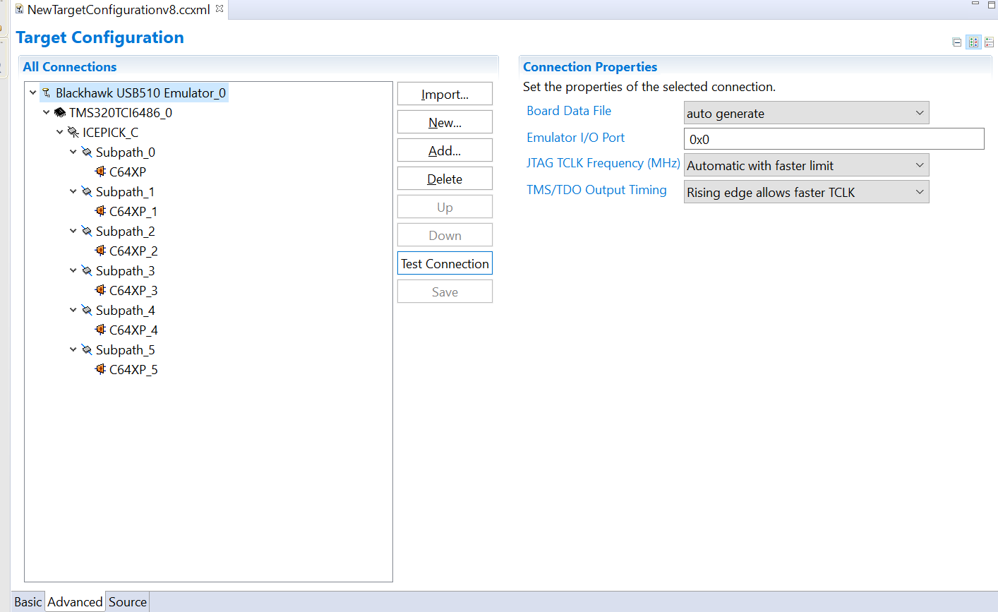
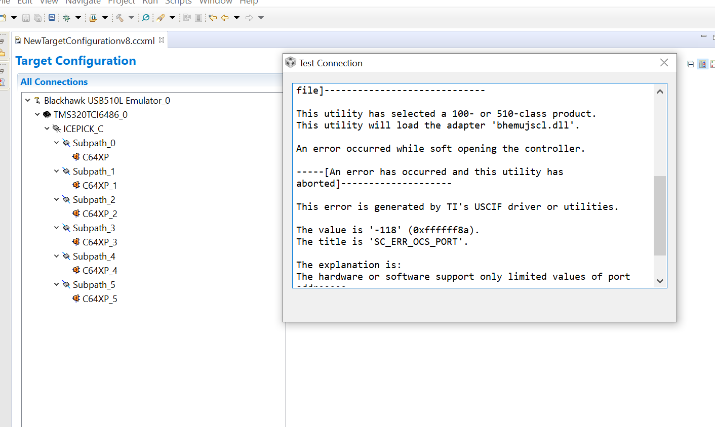
I'm attaching a screenshot of my target configuration and test connection result. Any help is much appreciated!
Thanks!
Test connection result:
[Start: Blackhawk USB510 Emulator_0]
Execute the command:
%ccs_base%/common/uscif/dbgjtag.exe -f %boarddatafile% -rv -o -F inform,logfile=yes -S pathlength -S integrity
[Result]
-----[Print the board config pathname(s)]------------------------------------
C:\Users\ADMINI~1\AppData\Local\TEXASI~1\
CCS\ti\2\0\BrdDat\testBoard.dat
-----[Print the reset-command software log-file]-----------------------------
This utility has selected a 100- or 510-class product.
This utility will load the adapter 'bhemujsc.dll'.
The library build date was 'Nov 21 2018'.
The library build time was '00:08:45'.
The library package version is '8.0.903.2'.
The library component version is '35.35.0.0'.
The controller does not use a programmable FPGA.
The controller has a version number of '1' (0x00000001).
The controller has an insertion length of '16' (0x00000010).
This utility will attempt to reset the controller.
This utility has successfully reset the controller.
-----[Print the reset-command hardware log-file]-----------------------------
The controller is the BitIO-TBC C-model.
The link from controller to target is unrecognised.
The controller cannot monitor the value on the EMU[0] pin.
The controller cannot monitor the value on the EMU[1] pin.
The controller cannot control the timing on output pins.
The controller will use falling-edge timing on output pins.
The utility logic is not currently detecting a power-loss.
-----[The log-file for the JTAG TCLK output generated from the PLL]----------
Test Size Coord MHz Flag Result Description
~~~~ ~~~~ ~~~~~~~ ~~~~~~~~ ~~~~ ~~~~~~~~~~~ ~~~~~~~~~~~~~~~~~~~
1 none - 01 00 500.0kHz - similar isit internal clock
2 none - 01 09 570.3kHz - similar isit internal clock
3 64 - 01 00 500.0kHz O good value measure path length
4 16 - 01 00 500.0kHz O good value auto step initial
5 16 - 01 0D 601.6kHz O good value auto step delta
6 16 - 01 1C 718.8kHz O good value auto step delta
7 16 - 01 2E 859.4kHz O good value auto step delta
8 16 + 00 02 1.031MHz O good value auto step delta
9 16 + 00 09 1.141MHz {O} good value auto step delta
10 64 - 01 29 820.3kHz O good value auto power initial
11 64 - 01 39 945.3kHz O good value auto power delta
12 64 + 00 01 1.016MHz O good value auto power delta
13 64 + 00 05 1.078MHz O good value auto power delta
14 64 + 00 07 1.109MHz O good value auto power delta
15 64 + 00 08 1.125MHz O good value auto power delta
16 64 + 00 08 1.125MHz O good value auto power delta
17 64 + 00 00 1.000MHz {O} good value auto margin initial
The first internal/external clock test resuts are:
The expect frequency was 500000Hz.
The actual frequency was 500000Hz.
The delta frequency was 0Hz.
The second internal/external clock test resuts are:
The expect frequency was 570312Hz.
The actual frequency was 569000Hz.
The delta frequency was 1312Hz.
In the scan-path tests:
The test length was 2048 bits.
The JTAG IR length was 24 bits.
The JTAG DR length was 4 bits.
The IR/DR scan-path tests used 17 frequencies.
The IR/DR scan-path tests used 500.0kHz as the initial frequency.
The IR/DR scan-path tests used 1.141MHz as the highest frequency.
The IR/DR scan-path tests used 1.000MHz as the final frequency.
-----[Measure the source and frequency of the final JTAG TCLKR input]--------
The frequency of the JTAG TCLKR input is measured as 1.000MHz.
The frequency of the JTAG TCLKR input and TCLKO output signals are similar.
The target system likely uses the TCLKO output from the emulator PLL.
-----[Perform the standard path-length test on the JTAG IR and DR]-----------
This path-length test uses blocks of 64 32-bit words.
The test for the JTAG IR instruction path-length succeeded.
The JTAG IR instruction path-length is 24 bits.
The test for the JTAG DR bypass path-length succeeded.
The JTAG DR bypass path-length is 4 bits.
-----[Perform the Integrity scan-test on the JTAG IR]------------------------
This test will use blocks of 64 32-bit words.
This test will be applied just once.
Do a test using 0xFFFFFFFF.
Scan tests: 1, skipped: 0, failed: 0
Do a test using 0x00000000.
Scan tests: 2, skipped: 0, failed: 0
Do a test using 0xFE03E0E2.
Scan tests: 3, skipped: 0, failed: 0
Do a test using 0x01FC1F1D.
Scan tests: 4, skipped: 0, failed: 0
Do a test using 0x5533CCAA.
Scan tests: 5, skipped: 0, failed: 0
Do a test using 0xAACC3355.
Scan tests: 6, skipped: 0, failed: 0
All of the values were scanned correctly.
The JTAG IR Integrity scan-test has succeeded.
-----[Perform the Integrity scan-test on the JTAG DR]------------------------
This test will use blocks of 64 32-bit words.
This test will be applied just once.
Do a test using 0xFFFFFFFF.
Scan tests: 1, skipped: 0, failed: 0
Do a test using 0x00000000.
Scan tests: 2, skipped: 0, failed: 0
Do a test using 0xFE03E0E2.
Scan tests: 3, skipped: 0, failed: 0
Do a test using 0x01FC1F1D.
Scan tests: 4, skipped: 0, failed: 0
Do a test using 0x5533CCAA.
Scan tests: 5, skipped: 0, failed: 0
Do a test using 0xAACC3355.
Scan tests: 6, skipped: 0, failed: 0
All of the values were scanned correctly.
The JTAG DR Integrity scan-test has succeeded.
[End: Blackhawk USB510 Emulator_0]
Target Configuration:-