This thread has been locked.

If you have a related question, please click the "Ask a related question" button in the top right corner. The newly created question will be automatically linked to this question.

CCS/EK-TM4C1294XL: Memory Map Prevented reading 0X01009B7C

Part Number: EK-TM4C1294XL
Other Parts Discussed in Thread: TM4C1294NCPDT

Tool/software: Code Composer Studio

Dear All, 

I'm facing few challenges during debugging the EK-TM4C129Xl with custom application. Please find the below attached files for the reference. 

Thanks,
Sai 

  • Dear All,

    Please find the below attachment for the reference. 

    Thanks,

    Sai 
  • Sai,

    Looking at the data sheet for that device there is no memory at that address.

    The debugger will be configured to prevent reading of those addresses.  That is why you get the message "Memory map prevented reading...".

    As to why the program execution has gone to that address I am not sure.  Does it go here immediately or does the debugger halt at main() when you first start the debug session?

    I will loop in the TM4C team to help.

    Regards,

    John

  • Dear John, 

    Thanks for the data-sheet. 

    I'm trying to debug the custom application and after executing few lines of code in main(). It halts the execution of code and brings the "" Memory Map Prevented from reading""". 

    Could you please explain more in detail about this error message? and suggest an alternative to overcome the halt during the debugging process ?


    Thanks,

    Sai 

  • It appears that while executing code, the program has branched to a location of unimplemented memory. If you did not get the error "Memory Map Prevented from reading" by, for example, disabling the memory map, you would have gotten an abort. I suggest you identify which line of C code generated the error. Then reset the device and run to that line of C code. Instead of C stepping from that point, try assembly language stepping. Look at the values in the CPU registers while doing this. Common problems are doing an indirect call with an incorrect address, or returning from a function with a corrupt stack value.

  • Dear Crosby, 

    Sure, I'll try debugging again with assembly code and record register values for analysis. Also, During debugging the step by step execution of code gets crashed from the main() program. Does it has any reason for it? Why does step by step process gets halted while debugging? Please let me know and thanks.

    Regards,

    Sai 

  • Dear Crosby,

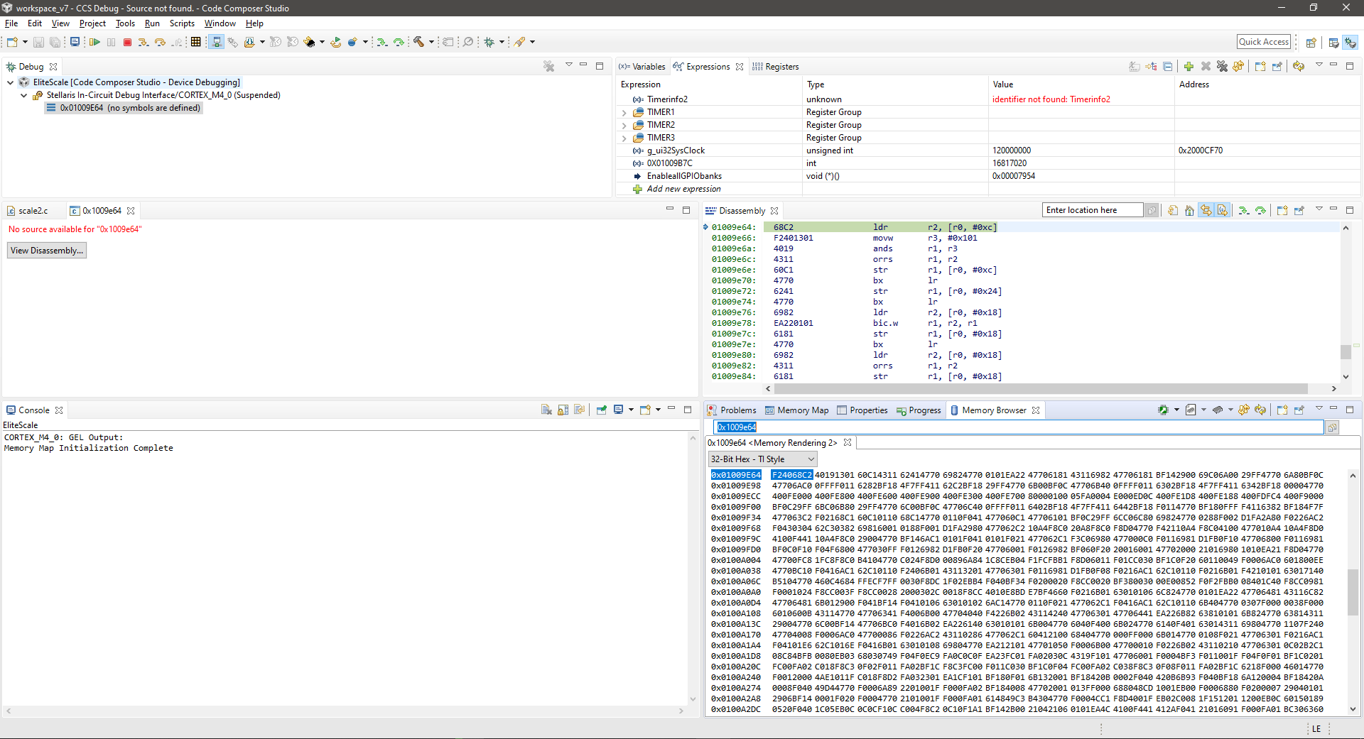
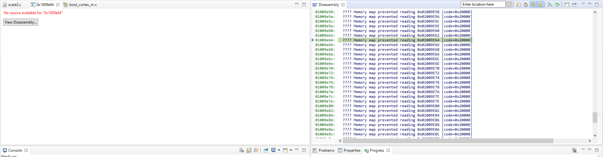
    Please find the below two files after assembly debugging. 

    1) Before error at Timer2_A step. 

    2) After executing the next step or exiting the Timer2_A. (error) ""Memory map prevented reading. I hope this helps. 

    I'm trying to enable Timer1A, Timer2A, Timer3A in my application. During execution, my application crashes at Timer2A. Could someone suggest something better solution? I hope above two attachment helps for analysis. 

    Best Regards,

    Sai 

  • JohnS said:
    Looking at the data sheet for that device there is no memory at that address.

    As noted in the thread CCS/TM4C1294NCPDT: Discrepancy between the ROM size specified in CCS GEL files and the actual ROM size in TM4C devices:

    Brian Willoughby said:
    On a related note, the Data Sheet for the TM4C1294[KN]CPDT has the wrong address for the ROM. Page 103 shows 0x02000000.0x02FFFFFF as the memory range for ROM, but as we know the ROM actually starts at 0x01000000.

    JohnS said:
    The debugger will be configured to prevent reading of those addresses. 

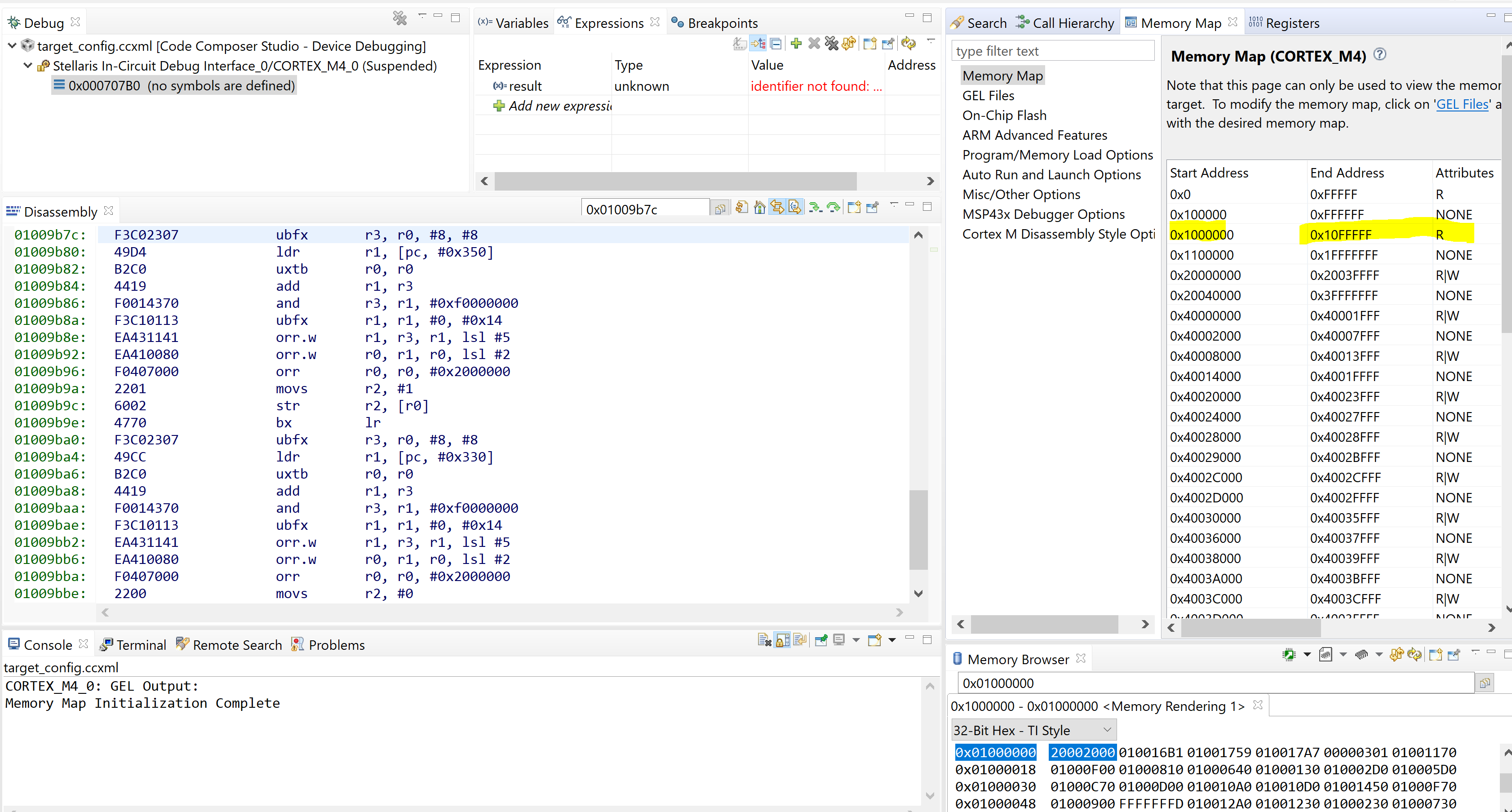
    From the above referenced thread, another issue is that while the ccs_base/emulation/gel/tm4c1294ncpdt.gel has the correct base address of 0x01000000 for the ROM, the size is smaller than the actual ROM. E.g. the CCS 10.1.1 ccs_base/emulation/gel/tm4c1294ncpdt.gel has:

        GEL_MapAddStr(0x01000000, 0, 0x00008c00, "R", 0);  /* ROM */

    Where as from previous tests, the ROM size was 0xe700 bytes for a TM4C1294NCPDT with ROM version 0x301.

    The above two things mean that when Sai got the "Memory Map Prevent from reading" errors at address 0x01009B7C the program counter was actually at a valid address in ROM.

    Is it possible to get the device datasheet and CCS GEL files updated to match the actual addresses of the TM4C ROM?

    I didn't find the actual ROM size specified; just created a program which probed ROM addresses to find the highest address which didn't cause a bus fault.

  • Chester,

    Thank you for pointing this out. I too was mislead by the table in the datasheet. I have entered an internal ticket against the datasheet to get this corrected with a note that it also applies to the CCS map files. Unfortunately there are no near term plans to update the datasheet.

  • Dear John, 

    Could you please give me some suggestions to overcome the program crash during debugging for EK-TM4C129XL from above? 

    Thanks,

    Sai 

  • Sai,

    Which version of CCS are you using? I do not see the issue you describe. Perhaps you have the wrong target configuration. I went back to CCS version 8.3 and see proper disassembly at the ROM address 0x01009b7c which you showed in your example.

  • Never mind, I see the issue in CCS v10. I will create an updated version of the file tm4c1294ncpdt.gel for you. Should take a couple of hours.

  • Hi Bob, 

    Currently, I'm using Code Composer 7.4.0 for the debugging the custom application. 

    Thanks,
    Sai 

  • Dear Bob, 

    Currently, I'm using Code Composer studio 7.4.0 for debugging custom application. 

    Best Regards,

    Sai  

  • Dear Bob, 

    I have searched the address in Memory Browser. The results are at the below and have a look at it once. Looking forward to hearing from you.

    Best Regards,

    Sai 

  • OK, I don't have that old version loaded on my machine. I only have versions 8, 9 and 10. (You might want to consider updating.)

    Check which GEL files you have loaded. From the top menu "Tools" -> "GEL Files". You should see something like this:

    Look for a file like:

    C:\ti\ccsv7\ccs_base\emulation\gel\tm4c1294ncpdt.gel. Replace it with the attached version and restart Code Composer.

    /cfs-file/__key/communityserver-discussions-components-files/81/tm4c1294ncpdt.gel

  • Dear Bob, 

    Thank you so much for the updated version on TM4C1294NCPDT.gel file. it has worked successfully. However, I can read the data in the disassembly and Memory browser. I still get an ""No source available for  "0x 1009e64". Could you please let me know? What exactly it means and how to fix it? 

    Please find the reference snippet for the understanding. 

    Best Regards,
    Sai 

  • Hi Sai,

    Your code has called a function that is in the ROM memory. The source code is not part of your project so the message is correct. Typically customers do not debug through the ROM functions. They typically CSTEP over them. However, there are occasions when you want to see what it happening inside a TivaWare function. One way to do this is to remove the "MAP_" or "ROM_" prefix from the function name. That way the object code will be pulled from the library instead of executing from the ROM. You will still get an error message about where to find the source, but you can then search for the source and find it in the TivaWare directory "C:\ti\TivaWare_C_Series-2.2.0.295\driverlib" (depending on which version of TivaWare you used). 

    I often use another method. If, for example, I want to debug through a TivaWare UART function, I will copy the file "C:\ti\TivaWare_C_Series-2.2.0.295\driverlib\uart.c" into my project. When I step into one of the UART functions, CCS can find the source.

    A third (more advanced) option is to import the CCS project from "C:\ti\TivaWare_C_Series-2.2.0.295\driverlib\ccs" and rebuild the driverlib.lib library file. This version will then have proper path information for the TivaWare source files on your machine. You must then point the linker to this version of the library. Again, call without the "MAP_" or "ROM_" prefix.

    While this is all good information to learn, I suspect that it is not helping you solve the original problem. Perhaps if you describe the original issue, such as the device does not return when I C-step into the function "xxxx", I might be able to give you some insight into what may be happenning.

  • Dear Bob, 

    Thank you for asking the source code. Please find the below code for the understanding. 

    I'm trying to initialize the all the target device parameters such as GPIO, TIMER1A, TIMER2A, TIMER3A and UART0 at PORTA in my main() loop. Up to the initialization of Timer1A the program executes fine and good. During the initialization of Timer2A, the program gets crash and I can't move further for debugging the code. Could you please give me an insight for the program crash. Looking forward to hearing from you with some suggestions.

    / This is the main loop that runs the application.
    //*****************************************************************************
    int main(void)
    {
          // Run from the PLL at 120 MHz.
          // Note: SYSCTL_CFG_VCO_240 is a new setting provided in TivaWare 2.2.x and
          // later to better reflect the actual VCO speed due to SYSCTL#22.
          //
          g_ui32SysClock = MAP_SysCtlClockFreqSet((SYSCTL_XTAL_25MHZ | SYSCTL_OSC_MAIN | SYSCTL_USE_PLL | SYSCTL_CFG_VCO_240), 120000000);
    
        // Enable all GPIO banks.
    
                MAP_SysCtlPeripheralEnable(SYSCTL_PERIPH_GPIOA);
                MAP_SysCtlPeripheralEnable(SYSCTL_PERIPH_GPIOB);
                MAP_SysCtlPeripheralEnable(SYSCTL_PERIPH_GPIOC);
                MAP_SysCtlPeripheralEnable(SYSCTL_PERIPH_GPIOD);
                MAP_SysCtlPeripheralEnable(SYSCTL_PERIPH_GPIOE);
                MAP_SysCtlPeripheralEnable(SYSCTL_PERIPH_GPIOJ);
                MAP_SysCtlPeripheralEnable(SYSCTL_PERIPH_GPIOK);
                MAP_SysCtlPeripheralEnable(SYSCTL_PERIPH_GPIOL);
                MAP_SysCtlPeripheralEnable(SYSCTL_PERIPH_GPIOM);
                MAP_SysCtlPeripheralEnable(SYSCTL_PERIPH_GPION);
    
    	// LED ports
    
                       MAP_GPIOPinTypeGPIOOutput(GPIO_PORTD_BASE, GPIO_PIN_0); // heartbeat/user led port out
                       MAP_GPIOPinTypeGPIOOutput(GPIO_PORTD_BASE, GPIO_PIN_1); // metric led port out
                       MAP_GPIOPinTypeGPIOOutput(GPIO_PORTD_BASE, GPIO_PIN_2); // english led port out
                       MAP_GPIOPinTypeGPIOOutput(GPIO_PORTD_BASE, GPIO_PIN_3); // male led port out
    
                       MAP_GPIOPinTypeGPIOOutput(GPIO_PORTC_BASE, GPIO_PIN_4);    // female led port out
                       MAP_GPIOPinTypeGPIOOutput(GPIO_PORTC_BASE, GPIO_PIN_5); // graphic led port out
                       MAP_GPIOPinTypeGPIOOutput(GPIO_PORTC_BASE, GPIO_PIN_6); // plain led port out
                       MAP_GPIOPinTypeGPIOOutput(GPIO_PORTC_BASE, GPIO_PIN_7); // enter led port out
    
                       MAP_GPIOPinTypeGPIOOutput(GPIO_PORTM_BASE, (GPIO_PIN_0 | GPIO_PIN_1 | GPIO_PIN_2 | GPIO_PIN_3));    // port out
                       MAP_GPIOPinTypeGPIOOutput(GPIO_PORTM_BASE, (GPIO_PIN_4 | GPIO_PIN_5 | GPIO_PIN_6)); // port out
    
                       MAP_GPIOPinTypeGPIOOutput(GPIO_PORTL_BASE, (GPIO_PIN_0 | GPIO_PIN_1 | GPIO_PIN_2)); // port out
                       MAP_GPIOPinTypeGPIOOutput(GPIO_PORTL_BASE, (GPIO_PIN_5 | GPIO_PIN_6 | GPIO_PIN_7)); // port out
                       MAP_GPIOPinTypeGPIOOutput(GPIO_PORTE_BASE, 0xff);   // dp leds port out
                       MAP_GPIOPinTypeGPIOOutput(GPIO_PORTN_BASE, GPIO_PIN_0); // heartbeat
    
          clrDp();
    
        // Configure SysTick for a periodic interrupt.
          MAP_SysTickPeriodSet(g_ui32SysClock/100);			// 10 msec 
    
          MAP_SysTickIntEnable();
          MAP_SysTickEnable();
    
    
        // Configure timer 1 for a periodic interrupt.
    
               MAP_SysCtlPeripheralEnable(SYSCTL_PERIPH_TIMER1);
               MAP_TimerConfigure(TIMER1_BASE, TIMER_CFG_PERIODIC);
               MAP_TimerLoadSet(TIMER1_BASE, TIMER_A, g_ui32SysClock / 10);   // 0.5 sec 
               MAP_IntEnable(INT_TIMER1A);
               MAP_TimerIntEnable(TIMER1_BASE, TIMER_TIMA_TIMEOUT);
               MAP_TimerEnable(TIMER1_BASE, TIMER_A);


    MAP_SysCtlPeripheralEnable(SYSCTL_PERIPH_TIMER2); MAP_TimerConfigure(TIMER2_BASE, TIMER_CFG_PERIODIC); MAP_TimerLoadSet(TIMER2_BASE, TIMER_A, g_ui32SysClock / 2); // 0.5 sec MAP_IntEnable(INT_TIMER2A); MAP_TimerIntEnable(TIMER2_BASE, TIMER_TIMA_TIMEOUT); MAP_TimerEnable(TIMER2_BASE, TIMER_A); MAP_GPIOPinWrite(GPIO_PORTN_BASE, GPIO_PIN_0, GPIOPinRead(GPIO_PORTN_BASE, GPIO_PIN_0) ^ GPIO_PIN_0);
    MAP_SysCtlPeripheralEnable(SYSCTL_PERIPH_TIMER3); MAP_TimerConfigure(TIMER3_BASE, TIMER_CFG_PERIODIC); MAP_TimerLoadSet(TIMER3_BASE, TIMER_A, g_ui32SysClock / 20); // 0.5 sec MAP_IntEnable(INT_TIMER3A); MAP_TimerIntEnable(TIMER3_BASE, TIMER_TIMA_TIMEOUT); MAP_TimerEnable(TIMER3_BASE, TIMER_A); // Configure timer 2 for a periodic interrupt. // Configure timer 3 for a periodic interrupt. //Sai Changed to 5 // Enable processor interrupts. MAP_IntMasterEnable(); // Enable the UART. MAP_GPIOPinConfigure(GPIO_PA0_U0RX); MAP_GPIOPinConfigure(GPIO_PA1_U0TX); MAP_GPIOPinTypeUART(GPIO_PORTA_BASE, GPIO_PIN_0 | GPIO_PIN_1); //UARTStdioInit(0); // Not available in TM4C129XL UARTStdioConfig(0, 115200, g_ui32SysClock); delay100Ms(1);

    Thanks,

    Sai 

  • When you stop the debugger after trying to CSTEP the line that enables timer 2, do you see it stuck here?

    //*****************************************************************************
    //
    // This is the code that gets called when the processor receives an unexpected
    // interrupt.  This simply enters an infinite loop, preserving the system state
    // for examination by a debugger.
    //
    //*****************************************************************************
    static void
    IntDefaultHandler(void)
    {
        //
        // Go into an infinite loop.
        //
        while(1)
        {
        }
    }
    

    If that is the case, you have not setup the vector for the Timer 1 interrupt service routine and you got an interrupt from timer 1 while you were trying to initialize timer 2. 

  • Dear Bob, 

    Yes, I got that information correct Bob. Please have a look at my whole source code. I have mentioned the interrupts respectively. Please let me know the what's the bug in my application.


    #include <stdbool.h> #include <stdint.h> #include <string.h> #include "inc.h" #include <inc/hw_types.h> #include <driverlib/debug.h> #include <driverlib/fpu.h> #include <driverlib/rom_map.h> // global variables uint32_t g_ui32SysClock; volatile unsigned int counter = 0; volatile unsigned int delaycnt = 0; volatile int ohmsReadFlag = 0; int blink = 0; char lastBuf[OHM_BUF_SIZE]; // copy of ohmBuf static char ohmBuf[OHM_BUF_SIZE]; static unsigned int ohmBptr = 0; // prototypes void delay100Ms(unsigned int); //***************************************************************************** // The error routine that is called if the driver library encounters an error. //***************************************************************************** #ifdef DEBUG void __error__(char *pcFilename, unsigned long ulLine) { } #endif //***************************************************************************** // The interrupt handler for the SysTick interrupt. //***************************************************************************** void SysTickIntHandler(void) { counter++; } //***************************************************************************** // The interrupt handler for the 1 timer A subtimer interrupt. // 1 per second used to control led blink rate //***************************************************************************** void Timer1AIntHandler(void) { // Clear the timer interrupt. ROM_TimerIntClear(TIMER1_BASE, TIMER_TIMA_TIMEOUT); delaycnt++; } //***************************************************************************** // The interrupt handler for the 2 timer A subtimer interrupt. // 1 per second used to control led blink rate //***************************************************************************** void Timer2AIntHandler(void) { // Clear the timer interrupt. TimerIntClear(TIMER2_BASE, TIMER_TIMA_TIMEOUT); if (blink) blink = 0; else blink = 1; if (blinkflags & GENBLINK) { maleLED(blink); femaleLED(blink ^ 1); showGender(blink); } if (blinkflags & PPWBLINK) { showPrt(blink); } if (blinkflags & GBLINK) { showGrip1(blink); } if (blinkflags & EBLINK) { enterLED(blink); } if (blinkflags & PBLINK) { plainLED(blink); graphicLED(blink ^ 1); } if (blinkflags & PGBLINK) { graphicLED(blink); } if (blinkflags & PPBLINK) { plainLED(blink); } } //***************************************************************************** // The interrupt handler for the 3 timer A subtimer interrupt. // 10 per second used to read keys //***************************************************************************** void Timer3AIntHandler(void) { // Clear the timer interrupt. TimerIntClear(TIMER3_BASE, TIMER_TIMA_TIMEOUT); keyUpdate(); // read the kbd every 0.1 sec MAP_IntMasterDisable(); if ((state == WAIT4WEIGHT) && (numKey == 1) && (weight_lb2 > STEPOFF)) { // static weight only dispWtFlag = 1; } } //***************************************************************************** // This is the main loop that runs the application. //***************************************************************************** int main(void) { // Set the clocking to run at 80 MHz from the PLL. // MAP_SysCtlClockSet(SYSCTL_SYSDIV_2_5 | SYSCTL_USE_PLL | SYSCTL_XTAL_16MHZ | SYSCTL_OSC_MAIN); // // Run from the PLL at 120 MHz. // Note: SYSCTL_CFG_VCO_480 is a new setting provided in TivaWare 2.1.4 and // later to better reflect the actual VCO speed due to SYSCTL#22. // g_ui32SysClock = SysCtlClockFreqSet((SYSCTL_XTAL_25MHZ | SYSCTL_OSC_MAIN | SYSCTL_USE_PLL | SYSCTL_CFG_VCO_480), 120000000); // Enable all GPIO banks. SysCtlPeripheralEnable(SYSCTL_PERIPH_GPIOA); SysCtlPeripheralEnable(SYSCTL_PERIPH_GPIOB); SysCtlPeripheralEnable(SYSCTL_PERIPH_GPIOC); SysCtlPeripheralEnable(SYSCTL_PERIPH_GPIOD); SysCtlPeripheralEnable(SYSCTL_PERIPH_GPIOE); SysCtlPeripheralEnable(SYSCTL_PERIPH_GPIOJ); SysCtlPeripheralEnable(SYSCTL_PERIPH_GPIOK); SysCtlPeripheralEnable(SYSCTL_PERIPH_GPIOL); SysCtlPeripheralEnable(SYSCTL_PERIPH_GPIOM); SysCtlPeripheralEnable(SYSCTL_PERIPH_GPION); // LED ports GPIOPinTypeGPIOOutput(GPIO_PORTD_BASE, GPIO_PIN_0); // heartbeat/user led port out GPIOPinTypeGPIOOutput(GPIO_PORTD_BASE, GPIO_PIN_1); // metric led port out GPIOPinTypeGPIOOutput(GPIO_PORTD_BASE, GPIO_PIN_2); // english led port out GPIOPinTypeGPIOOutput(GPIO_PORTD_BASE, GPIO_PIN_3); // male led port out GPIOPinTypeGPIOOutput(GPIO_PORTC_BASE, GPIO_PIN_4); // female led port out GPIOPinTypeGPIOOutput(GPIO_PORTC_BASE, GPIO_PIN_5); // graphic led port out GPIOPinTypeGPIOOutput(GPIO_PORTC_BASE, GPIO_PIN_6); // plain led port out GPIOPinTypeGPIOOutput(GPIO_PORTC_BASE, GPIO_PIN_7); // enter led port out GPIOPinTypeGPIOOutput(GPIO_PORTM_BASE, (GPIO_PIN_0 | GPIO_PIN_1 | GPIO_PIN_2 | GPIO_PIN_3)); // port out GPIOPinTypeGPIOOutput(GPIO_PORTM_BASE, (GPIO_PIN_4 | GPIO_PIN_5 | GPIO_PIN_6)); // port out GPIOPinTypeGPIOOutput(GPIO_PORTL_BASE, (GPIO_PIN_0 | GPIO_PIN_1 | GPIO_PIN_2)); // port out GPIOPinTypeGPIOOutput(GPIO_PORTL_BASE, (GPIO_PIN_5 | GPIO_PIN_6 | GPIO_PIN_7)); // port out GPIOPinTypeGPIOOutput(GPIO_PORTE_BASE, 0xff); // dp leds port out GPIOPinTypeGPIOOutput(GPIO_PORTN_BASE, GPIO_PIN_0); // heartbeat clrDp(); // Configure SysTick for a periodic interrupt. SysTickPeriodSet(g_ui32SysClock/100); // 10 msec // Sai Changed to 1msec SysTickIntEnable(); SysTickEnable(); // Configure timer 1 for a periodic interrupt. SysCtlPeripheralEnable(SYSCTL_PERIPH_TIMER1); TimerConfigure(TIMER1_BASE, TIMER_CFG_PERIODIC); TimerLoadSet(TIMER1_BASE, TIMER_A, g_ui32SysClock / 10); // 0.5 sec //Sai Changed to 100msec IntEnable(INT_TIMER1A); TimerIntEnable(TIMER1_BASE, TIMER_TIMA_TIMEOUT); TimerEnable(TIMER1_BASE, TIMER_A); SysCtlPeripheralEnable(SYSCTL_PERIPH_TIMER2); TimerConfigure(TIMER2_BASE, TIMER_CFG_PERIODIC); TimerLoadSet(TIMER2_BASE, TIMER_A, g_ui32SysClock / 2); // 0.5 sec //Sai Changed to 100msec IntEnable(INT_TIMER2A); TimerIntEnable(TIMER2_BASE, TIMER_TIMA_TIMEOUT); TimerEnable(TIMER2_BASE, TIMER_A); GPIOPinWrite(GPIO_PORTN_BASE, GPIO_PIN_0, GPIOPinRead(GPIO_PORTN_BASE, GPIO_PIN_0) ^ GPIO_PIN_0); //blink the LED SysCtlPeripheralEnable(SYSCTL_PERIPH_TIMER3); TimerConfigure(TIMER3_BASE, TIMER_CFG_PERIODIC); TimerLoadSet(TIMER3_BASE, TIMER_A, g_ui32SysClock / 20); // 0.5 sec //Sai Changed to 100msec IntEnable(INT_TIMER3A); TimerIntEnable(TIMER3_BASE, TIMER_TIMA_TIMEOUT); TimerEnable(TIMER3_BASE, TIMER_A); // Configure timer 2 for a periodic interrupt. // Configure timer 3 for a periodic interrupt. // Enable processor interrupts. IntMasterEnable(); // Enable the UART. GPIOPinConfigure(GPIO_PA0_U0RX); GPIOPinConfigure(GPIO_PA1_U0TX); GPIOPinTypeUART(GPIO_PORTA_BASE, GPIO_PIN_0 | GPIO_PIN_1); //UARTStdioInit(0); // Not available in TM4C129XL UARTStdioConfig(0, 115200, g_ui32SysClock); delay100Ms(1);

    Thanks,

    Sai 

  • Did you modify startup_ccs.c to add your interrupt routines to the vector table? When you have a small project that you want someone to review it is better to use the CCS "File" -> "Export", "General", "Archive File" to export the entire project into a .zip file and then attach it to the thread. This will then include all of the files used and the options. 

  • Dear Bob, 

    Yes, I was missing those Specific Timer1A, Timer2A, Timer3A and UART3 interrupt handler in the Startup File. Thanks for the suggestion throughout the process and thanks for teaching me the debugging lessons as well. 


    extern void SysTickIntHandler(void);
    extern void UART3IntHandler(void);
    extern void Timer1AIntHandler(void);
    extern void Timer2AIntHandler(void);
    extern void Timer3AIntHandler(void);

    SysTickIntHandler, // The SysTick handler Timer1AIntHandler, // Timer 1 subtimer A Timer2AIntHandler, // Timer 2 subtimer A Timer3AIntHandler, // Timer 3 subtimer A UART3IntHandler, // UART3 Rx and Tx

    Best Regards,

    Sai