This thread has been locked.

If you have a related question, please click the "Ask a related question" button in the top right corner. The newly created question will be automatically linked to this question.

CCS/TIDA-00961: The unusual PWM output for CRM totem-pole PFC

Part Number: TIDA-00961

Tool/software: Code Composer Studio

Hello, recently I have been studying the TIDA-00961 [High-Efficiency, 1.6-kW, High-Density, GaN-Based, 1-MHz CrM Totem-Pole PFC Converter Reference] and met many questions.

Firstly, I will tell the change that I hava made based on the Reference CCS project. All changes are in File SETTING.H. Since I donn't need too high frequency, so I lower the MIN_PFC_PWM_SWITCHING_FREQUENCY to 20*1000 and MAX_PFC_PWM_SWITCHING_FREQUENCY to 200*1000. However, something seems to be wrong that the PWM cannot refresh. So I changed PFC_PWM_PERIOD to 19*1000, then the switching frequency seems to be right.

Fig 01. 02.  the constant frequency while the TBPRD is refreshing

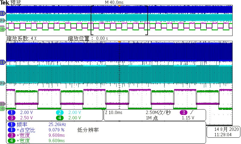
Secondly, I have verified the feasibility in DC/DC condition with current and voltage loop closed. However, when I change it to AC/DC with closed current loop, the PWM is wrong again which is shown as below.

Finally, since the author of the CCS project is Hrishi Nene, I will very appreciate it if he/she can anwser my questions. Of course, if my CCS project and schematic are needed please tell me, I can send them to you.

Fig 03.  the wrong PWM (high frequency)

The problem confused me for a long time and the project is very very important to me. 

Thank you very very much.

  • Hello, I changed my schematic and it's different from the TIDA-00961 schematic.

    Now I can sample the input 50Hz current or the triangular inductor current, but only one of them. So I have two ways to go, but both ways need to change the control code.

    Firstly, I use the output of the inner current loop to calculate Ton and Toff, and don't care if ZVS is achieved every switching frequency. I think if the 50Hz input current can be controlled then the inductor can be controlled as triangular wave. But I don't know if this can be carried out sucessfully, could you give me some reference designs?

    Secondly, the ZCD siganl of inductor current is used to achieve triangular wave. The Ton is calculated, then make the PWM-out closed. The voltage loop is only needed. But I don't have any reference code project.

    Many thanks in advance for your reply.

    Best regards.

    Bryce

  • Hi Bryce,

    Thanks for your detailed description. 

    I have some initial questions for my understanding.

    1. Did you change anything else in the code other than the min and max freq(especially for your first issue: wrong PWM)?

    2. What did you change in the hardware? Could you explain in high level(like certain sensing circuit or etc)?

    3. When you say PWM is not refreshing, could you elabarate what happens exactly? 

    Regards,

    Chen

  • Hi, Chen

    Thanks for your reply.

    Q1: I also changed the GPIOs for ePWM port since the DSP is different. And ADC sense gain. But they are still correspond to the original code.

    Q2: About the hardware, now I only sense the Vout, uac and iac. 

    Q3: I can see the TBPRD of the ePWM registers is changing and refreshing, but the output PWM on the board is a constant frequency. And I don't know why it's the constant number.

    Regards,

    Bryce

  • Ok, Thanks Bryce. Since these are very detailed questions related to the code, I will try to take a deep look at the issue and get back to you early next week.

    Regards,

    Chen

  • Thanks very much.

    If my ccs project and schematic are needed, please let me know.

    Best Regards,

    Bryce