This thread has been locked.

If you have a related question, please click the "Ask a related question" button in the top right corner. The newly created question will be automatically linked to this question.

CCS/TIDA-00961: Problem that PWM ISR interrupts will not be generated in Build1

Part Number: TIDA-00961


Tool/software: Code Composer Studio

Hello, I have one question about TIDA-00961.

I made the CRM Totem-Pole PFC hardware by referring to the TIDA-00961 schematic.

Using this hardware, I'm currently testing open-loop operation in Build 1 with DC input .

Since I want to operate with a lower switching frequency, I changed

 MIN_PFC_PWM_SWITCHING_FREQUENCY to 35 * 1000 and

 MAX_PFC_PWM_SWITCHING_FREQUENCY to 200 * 1000

in "pfc2philtrmttpl_settings.h" file.

When making the above changes, the PWM ISR interrupts will not be generated suddenly.

And even if the value of the variable "new_ton_calc" is changed, the gate pulse width becomes a fixed value and does not change.

The waveforms are shown below when the PWM ISR interrupts are stopped.

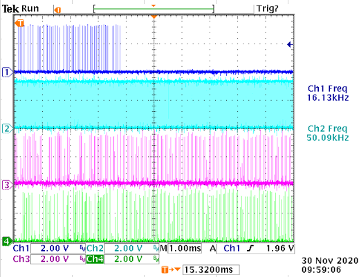
Figure: Waveforms when PWM ISR interrupts are stopped

Ch1:PWM ISR interrupts flag

Ch2:Fast Control ISR interrupts flag

Ch3:LS_GATE1(Low-side drive signal for phase 1HB)

Ch4:LS_GATE2(Low-side drive signal for phase 2HB)

What are the possible causes of this problem?

Best regards,

Keita

  • One of our team member will get back to you on this soon.

    Shamim

  • Hi Keita,

    Sorry for the late reply. Are you using the non-powerSUITE version of code? In other words, are you changing 

    "MIN_PFC_PWM_SWITCHING_FREQUENCY to 35 * 1000" in the code directly or through the GUI page?

    If you directly change in the code, that can explain the missing ISR. Because you also need to change the code below which is related to where the ISR is set.

    "#define PFC_PWM_PERIOD (PWMSYSCLOCK_FREQ)/((float32_t)200*1000) //Initial Period"

    Regard,

    Chen

  • Hi, Chen.

    Thanks for your reply.


    Yes, I'm now using the nonpowerSUITE version of code.

    As you pointed out above, the PWM ISR missing no longer occurs when I changed the value of PFC_PWM_PERIOD according to the value of MIN_PFC_PWM_SWITCHING_FREQUENCY.

    Figure: Waveforms when PFC_PWM_PERIOD is changed to (PWMSYSCLOCK_FREQ)/((float32_t)35*1000)

    Ch1:PWM ISR interrupts flag

    Ch2:Fast Control ISR interrupts flag

    Ch3:LS_GATE1(Low-side drive signal for phase 1HB)

    Ch4:LS_GATE2(Low-side drive signal for phase 2HB)

    To operate the circuit board safely, I would like to know under what conditions the PWM ISR missing occurs.

    As shown in the figure above, the frequency of the Fast Control ISR was lowered from 50kHz to 8.75kHz by changing the value of PFC_PWM_PERIOD.

    On the other hand, PWM ISR interrupts are considered to occur in the range of minimum 11.7kHz (35kHz / 3) and maximum 66.7kHz (200kHz / 3) since they are generated once every 3rd switching frequency event.

    Is it a necessary condition to keep the frequency of the Fast Control ISR lower than the minimum frequency of the PWM ISR to prevent the PWM ISR missing?

    Or what other conditions can be considered to prevent this?

    Best regards,

    Keita

  • Hi Keita,

    I think they are independent. You could check the source of each ISR in the code. The PWM ISR is triggered based on the EPWM module and CMPC value. Previously you didn't see the PWM ISR because of the large CMPC value which is set to be related to the period. As long as the correct CMPC is set, the PWM ISR should be there. 

    And same thing applies to fast control ISR which you could check the ISR source accordingly.

    Regards,

    Chen

  • Hi, Chen.
    Thanks for your reply.


    I agree that the PWM ISR should be generated if the correct CMPC value is set.
    So I checked if the CMPC was larger than the period value when the PWM ISR missing occurred.
    I added the following code at the beginning of the Control ISR code in "pfc2philtrmttpl_main.c" file.


    if((EPWM_getTimeBasePeriod(HIGH_FREQ_PWM1_BASE)) > (EPWM_getCounterCompareValue(HIGH_FREQ_PWM1_BASE, EPWM_COUNTER_COMPARE_C)))
       {
          GPIO_writePin(13,1);
       }
       else
       {
          GPIO_writePin(13,0);
       }


    The results are shown below.

    Figure: Waveforms whether the EPWM2 CMPC is larger than the period value when the PWM ISR missing occurs

        Ch1:PWM ISR interrupts flag
        Ch2:Fast Control ISR interrupts flag
        Ch3:Flag that is high when CMPC < PRD and low when CMPC ≥ PRD

    In my examination, it seems that the CMPC is always smaller than the period value, and the correct CMPC is set.

    As another investigation, I changed the CMPC settings by increasing the values of the variables "chng_var" in the "pfc2philtrmttpl_main.c" file.
    Increasing the value of chng_var from 40 (default) makes the PWM ISR missing less likely, and never happens when chng_var > 125.
    From this result, I think the PWM ISR missing is related to the timing when the PWM ISR interrupt is generated.

    In the code of TIDA-00961, the one shot global load pulse is generated by the following command in the pwmISR function.
     EPWM_setGlobalLoadOneShotLatch(HIGH_FREQ_PWM1_BASE); 
    Isn't it possible that an error may occur if the timing of this pulse generation and the timing when the EPWM2 counter reaches the period value match?

    Please let me know if you have any thoughts on the above matter.

    Best regards,
    Keita

  • Hi Keita,

    Sorry for the late reply due to the holiday. All load strobes are blocked until GLDCTL2 OSHTLD is written with 1 based on the TRM. So in that case, I think the strobe will not go through if they happen exactly at the same time.

    Regards,

    Chen