This thread has been locked.

If you have a related question, please click the "Ask a related question" button in the top right corner. The newly created question will be automatically linked to this question.

CCS/CC2652R: CC2652R custom board does not flash

Part Number: CC2652R
Other Parts Discussed in Thread: LAUNCHXL-CC26X2R1, , UNIFLASH, SIMPLELINK-2-4GHZ-DESIGN-REVIEWS, CCSTUDIO

Tool/software: Code Composer Studio

Hello everyone,

I developed a custom board using some of the reference designs of the CC2652R. The problem is that when I try to flash the memory using the XDS110 USB Debug Probe_0 built in the LaunchXL-CC26X2R1 I get the following error:

Cortex_M4_0: GEL Output: Memory Map Initialization Complete.
IcePick_C: Error connecting to the target: (Error -242 @ 0x0) A router subpath could not be accessed. The board configuration file is probably incorrect. (Emulation package 9.2.1.00042)

I do not think it may be hardware issue or a bad uC since I am getting correct voltages in the VDDR and in the DCOUPL pins.

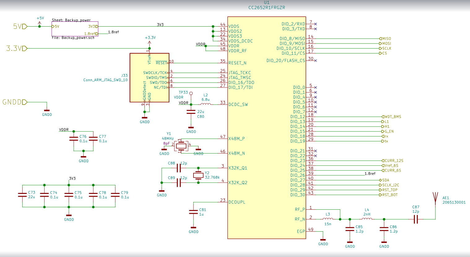
Please find attached the schematic, I know there is a pull-up resistor missing in the RESET pin, but I already added it.

I also changed the targetConfigs for using cJatg of 4 pins.

I am using CCS 10.1.1.000004

Any ideas?

Regards,

Sergio Bacca

  • Just in case the schematic file does not appear in the previous post

  • Hi Sergio,

    Inside CCSTUDIO, did you change the targetConfigs/CC2652R1F3.ccxml for cJTAG (1149.7) 4-pin standard mode?  have you tried using FLASH-PROGRAMMER-2 or UNIFLASH to program the board?  I also recommend submitting your custom board design to SIMPLELINK-2-4GHZ-DESIGN-REVIEWS and referencing the LAUNCHXL-CC26X2R1 design files and SWRA640.

    Regards,
    Ryan

  • Hello Ryan,

    Thank you for your answer. Yes I did try that, and I kept on getting the same error. However, I discovered the problem which I want to explain since I have read other people have had similar issues. Someone mentioned a pin missing alignment in an old post as the root cause. Indeed this was the problem I had. If you intend to solder this package by hand, it is quite challenging to align if you use a footprint with longer pads than the recommended one. I usually do this when I am prototyping for been able to use the soldering iron for reinforced with more soldering some pins; this happens when I do not have a stencil. This package is very small and has two small marks in the sides that can be confused with pads during inspection which leads to misalignment.

    I guess all the time it was a bad soldering problem. What worked for me was to perfectly align it and only solder the thermal pad with a heat gun, then make sure about the alignment, apply solder paste to the pins and push the solder paste with a fine iron tip until I can see the contact shining in the side using a magnifying glass. I guess if you have the proper stencil, smaller pads, and may be a pick and place with camera, your life will be easier.

    Thanks again!

    Sergio Bacca