Other Parts Discussed in Thread: C2000WARE
Tool/software: Code Composer Studio
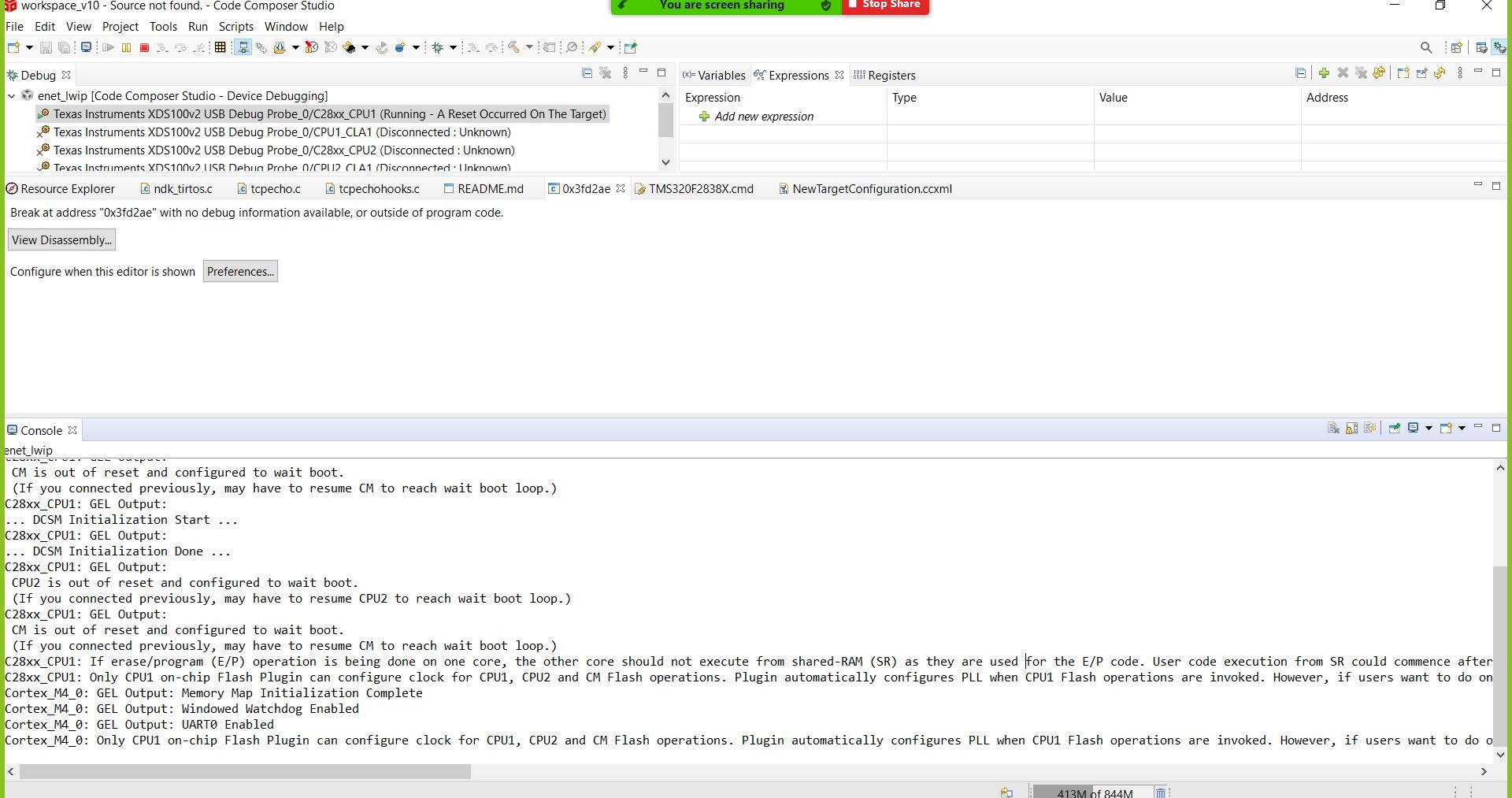
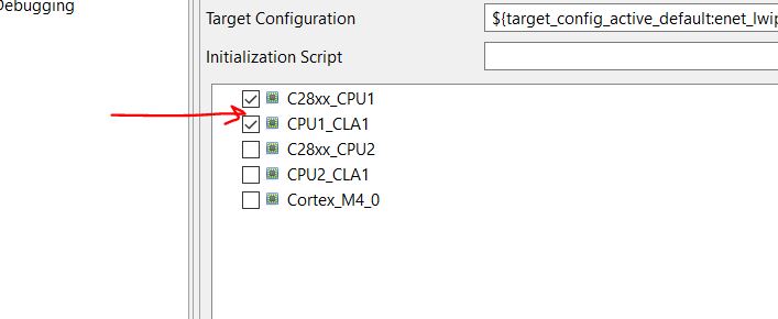
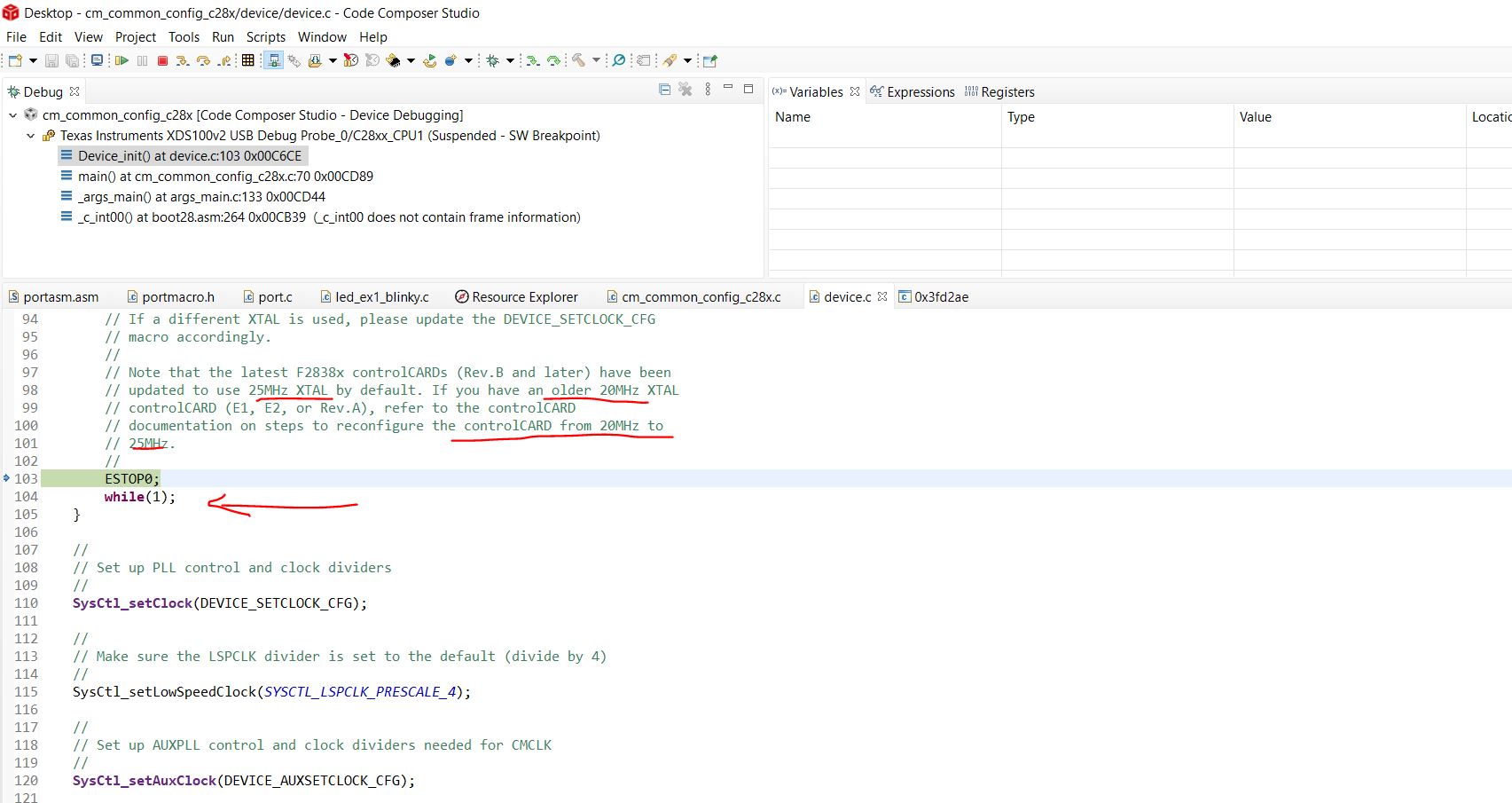
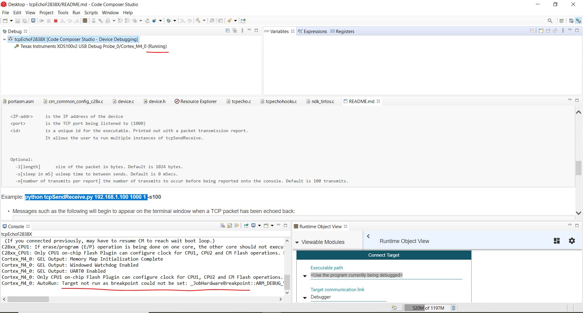
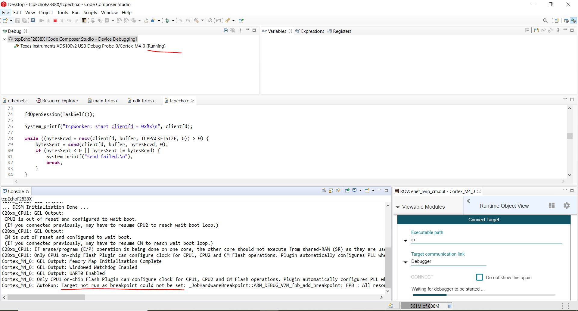
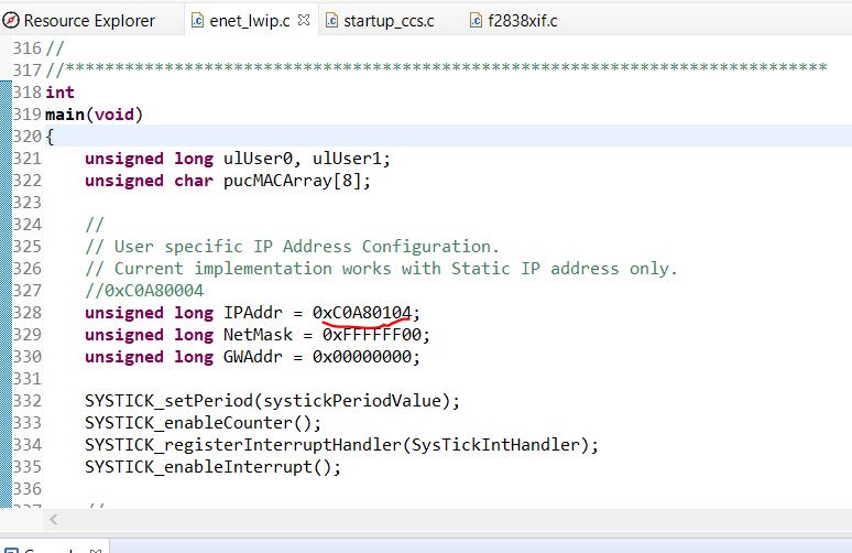
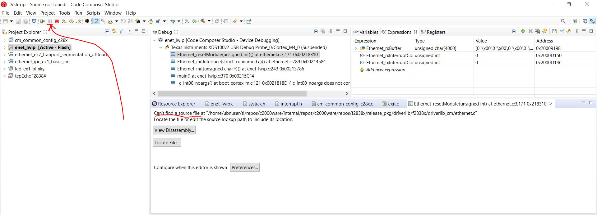
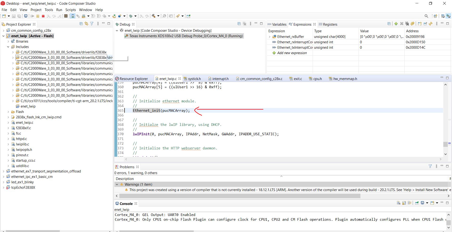
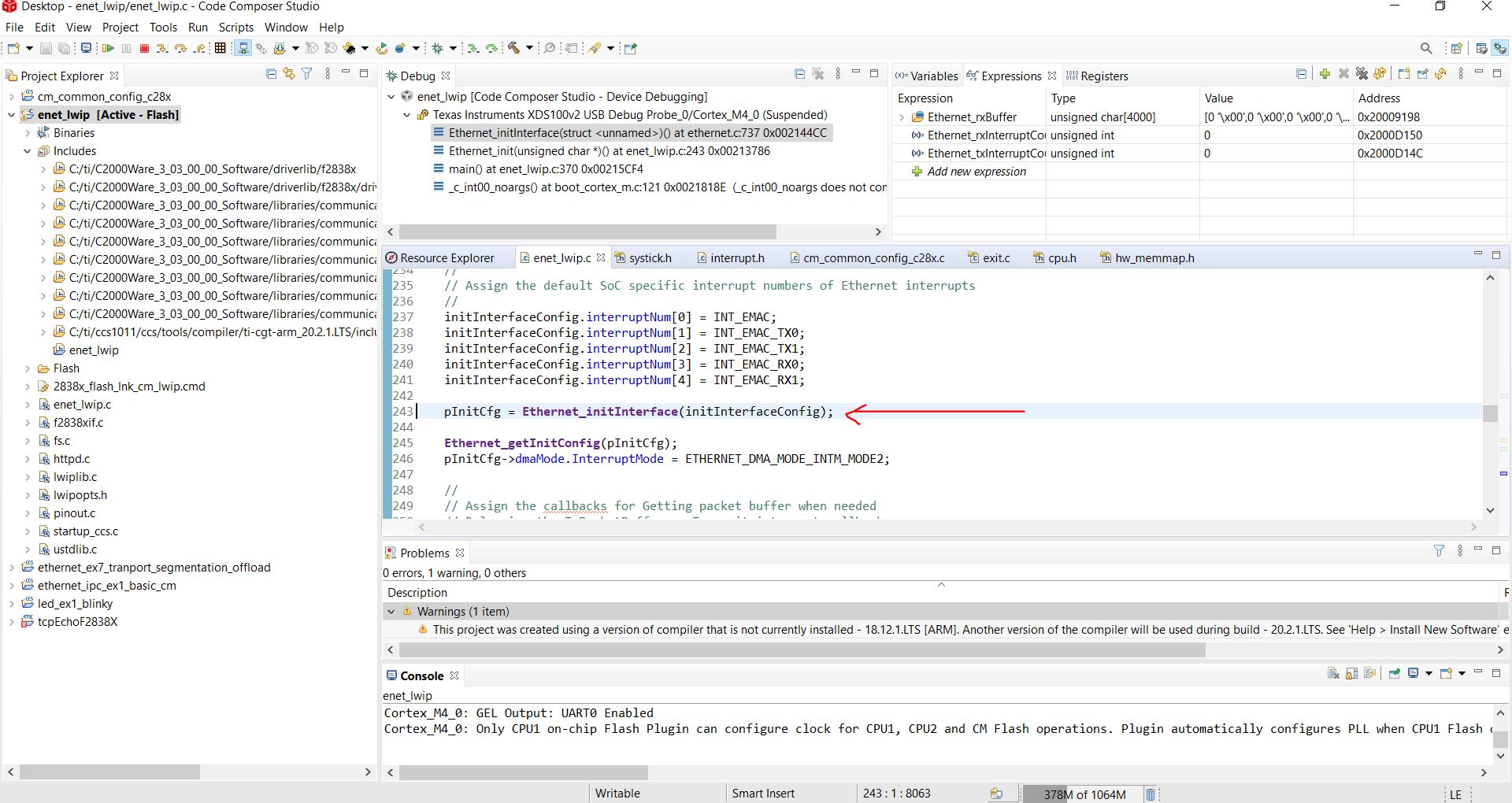
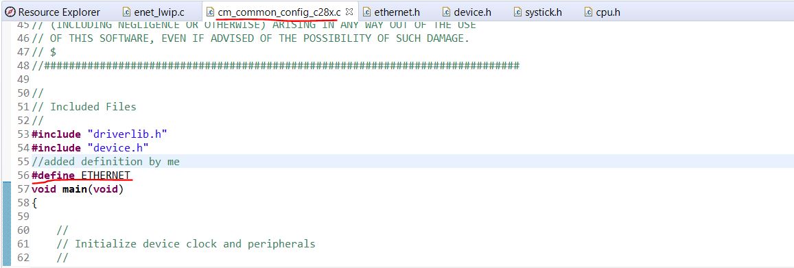
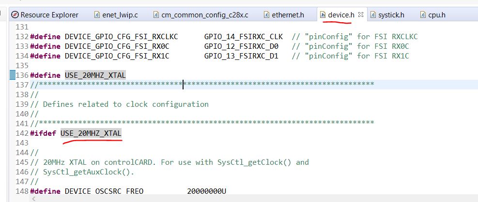
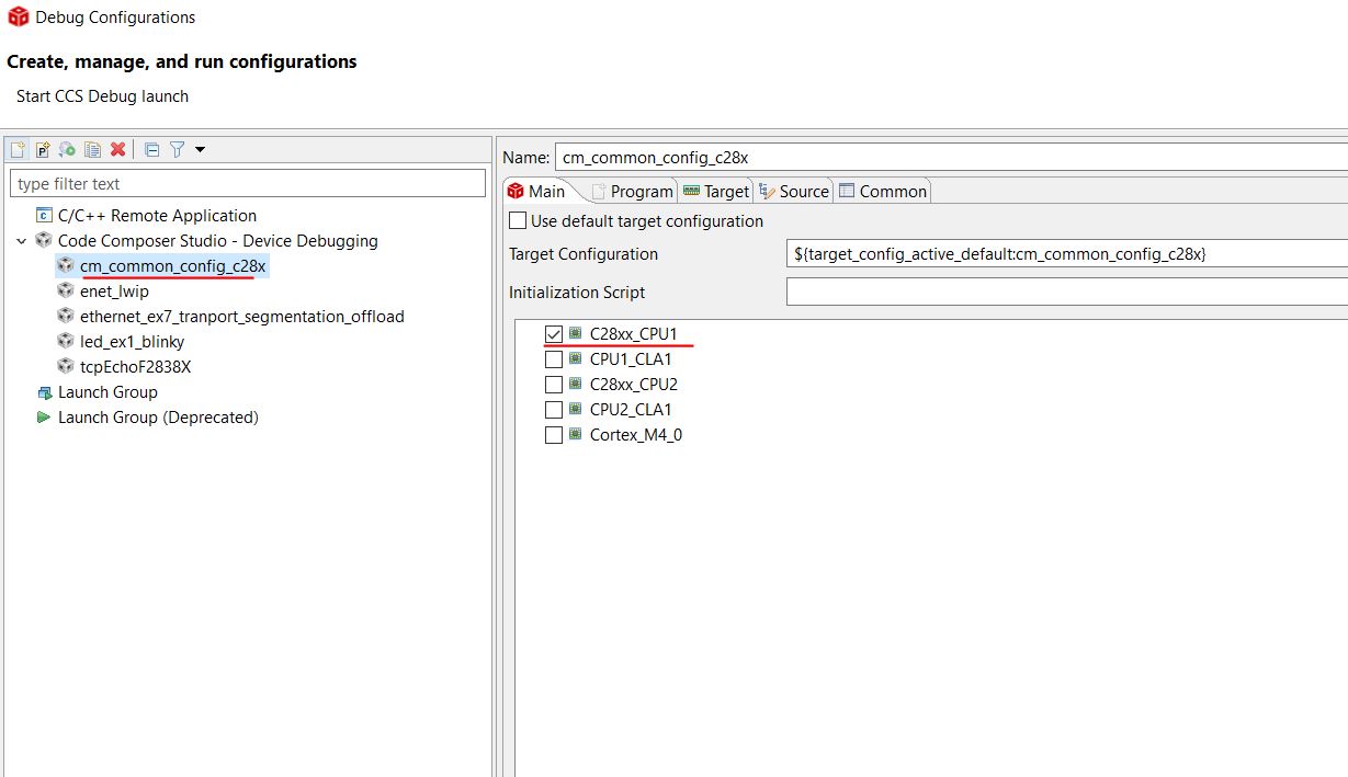
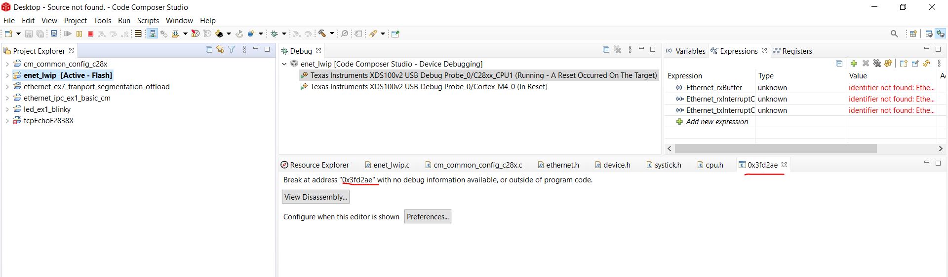
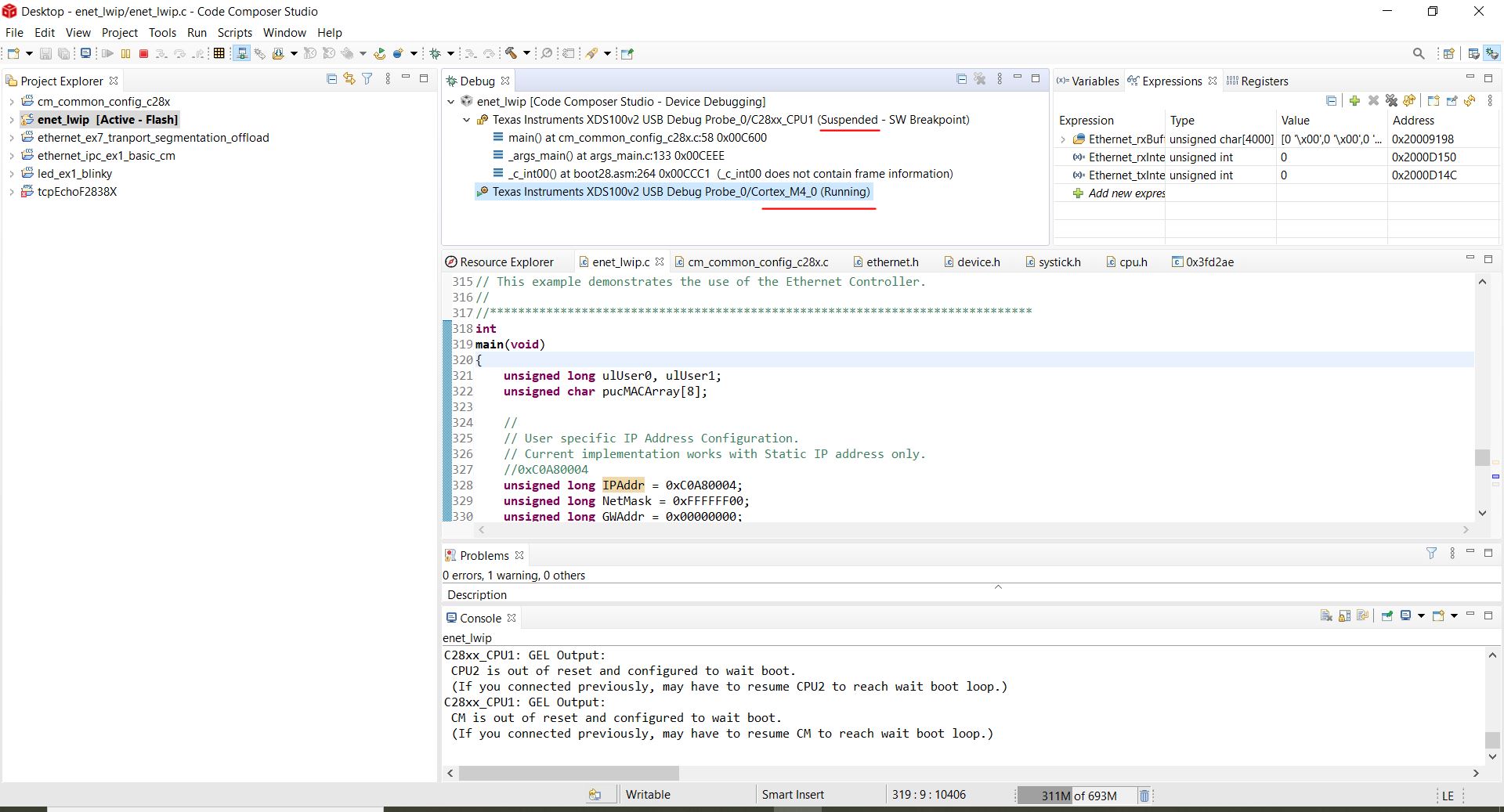
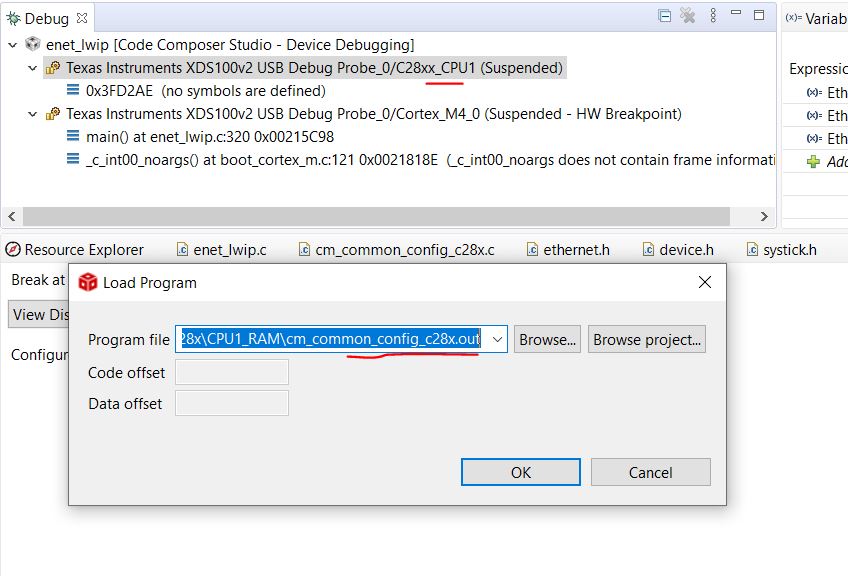
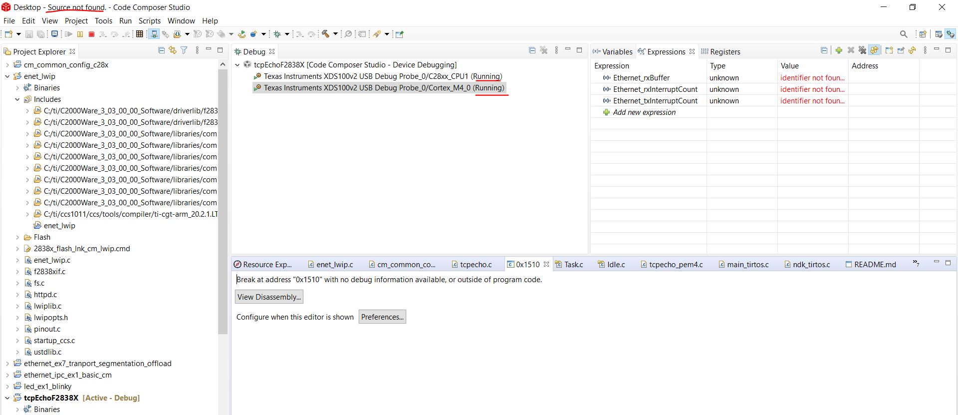
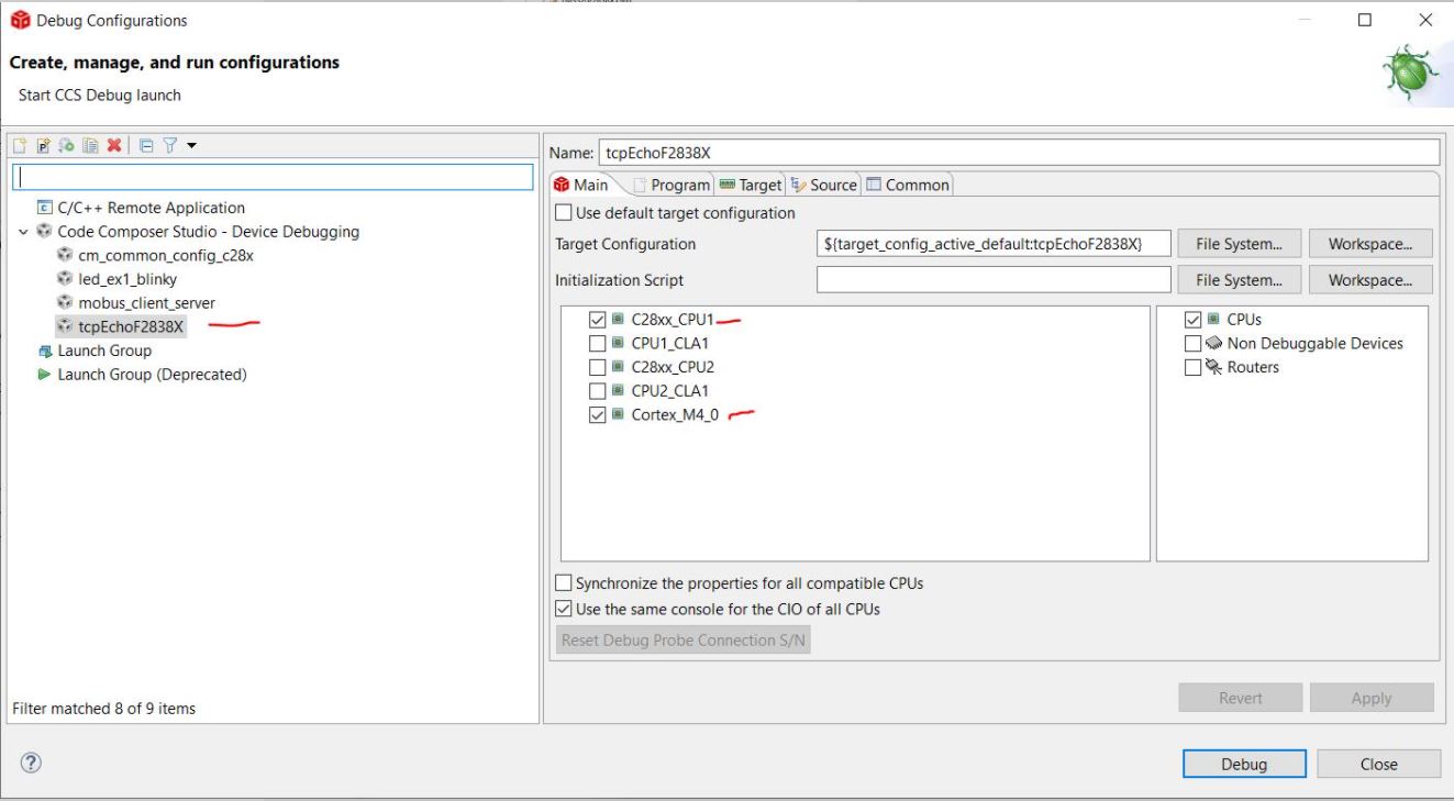
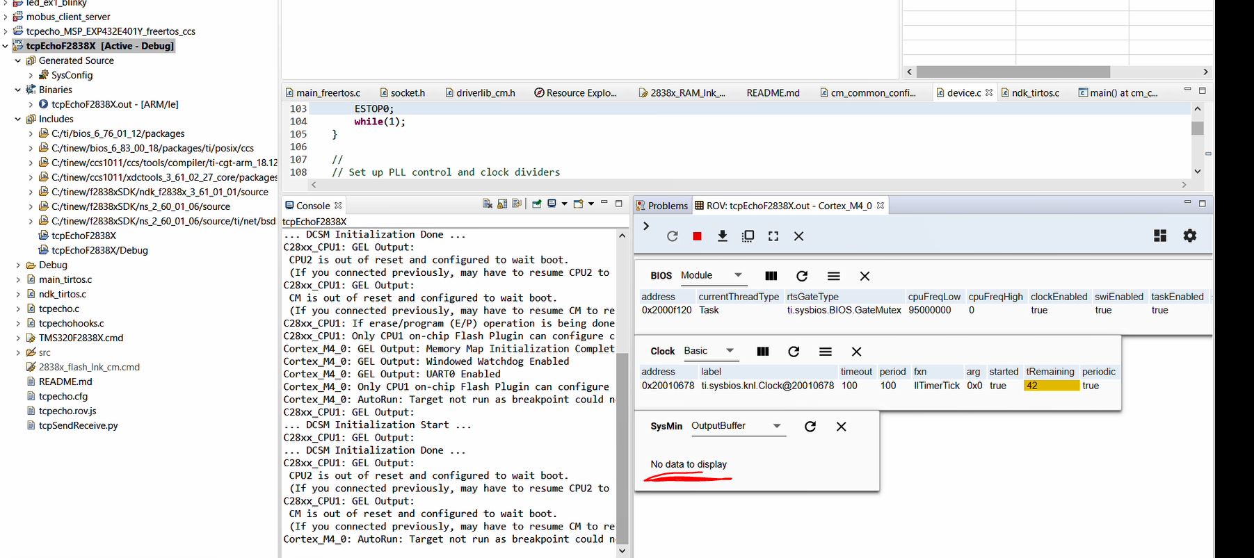
Hello, I have a TMS320F28388D rev MCU063A with docking station and am trying to make the tcp echo example build. I am getting the issue below. I can build fine but not run the code. It also says the source is not found at the top left of the image. I even tried creating a new target config file but same issue

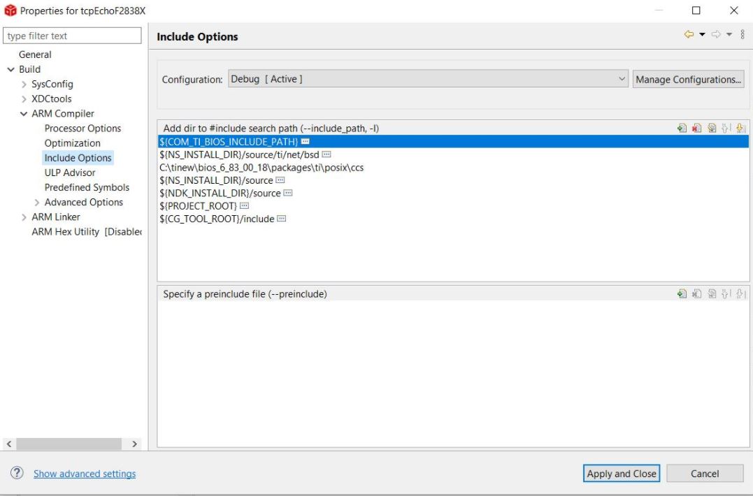
Include paths:

Console Output:
C28xx_CPU1: GEL Output:
Memory Map Initialization Complete
C28xx_CPU1: GEL Output:
... DCSM Initialization Start ...
C28xx_CPU1: GEL Output:
... DCSM Initialization Done ...
C28xx_CPU1: GEL Output:
CPU2 is out of reset and configured to wait boot.
(If you connected previously, may have to resume CPU2 to reach wait boot loop.)
C28xx_CPU1: GEL Output:
CM is out of reset and configured to wait boot.
(If you connected previously, may have to resume CM to reach wait boot loop.)
C28xx_CPU1: GEL Output:
... DCSM Initialization Start ...
C28xx_CPU1: GEL Output:
... DCSM Initialization Done ...
C28xx_CPU1: GEL Output:
CPU2 is out of reset and configured to wait boot.
(If you connected previously, may have to resume CPU2 to reach wait boot loop.)
C28xx_CPU1: GEL Output:
CM is out of reset and configured to wait boot.
(If you connected previously, may have to resume CM to reach wait boot loop.)
C28xx_CPU1: If erase/program (E/P) operation is being done on one core, the other core should not execute from shared-RAM (SR) as they are used for the E/P code. User code execution from SR could commence after both flash banks are programmed.
C28xx_CPU1: Only CPU1 on-chip Flash Plugin can configure clock for CPU1, CPU2 and CM Flash operations. Plugin automatically configures PLL when CPU1 Flash operations are invoked. However, if users want to do only CPU2 or CM Flash operations without doing a prior CPU1 operation in the current session, they should click on 'Configure Clock' button in CPU1's on-chip Flash Plugin before invoking CPU2 and CM Flash operations. When this button is used, Flash Plugin will configure the clock for CPU1/CPU2 at 190MHz and CM at 95MHz using INTOSC2 as the clock source. Plugin will leave PLL config like this and user application should configure the PLL as required by application.
Cortex_M4_0: GEL Output: Memory Map Initialization Complete
Cortex_M4_0: GEL Output: Windowed Watchdog Enabled
Cortex_M4_0: GEL Output: UART0 Enabled
Cortex_M4_0: Only CPU1 on-chip Flash Plugin can configure clock for CPU1, CPU2 and CM Flash operations. Plugin automatically configures PLL when CPU1 Flash operations are invoked. However, if users want to do only CPU2 or CM Flash operations without doing a prior CPU1 operation in the current session, they should click on 'Configure Clock' button in CPU1's on-chip Flash Plugin before invoking CPU2 and CM Flash operations. When this button is used, Flash Plugin will configure the clock for CPU1/CPU2 at 190MHz and CM at 95MHz using INTOSC2 as the clock source. Plugin will leave PLL config like this and user application should configure the PLL as required by application.
Cortex_M4_0: AutoRun: Target not run as breakpoint could not be set: _JobHardwareBreakpoint::ARM_DEBUG_V7M_fpb_add_breakpoint: FPB : All resources are in use.[25062]