This thread has been locked.

If you have a related question, please click the "Ask a related question" button in the top right corner. The newly created question will be automatically linked to this question.

CCS/UCD3138ALLCEVM150: UCD3138ALLCEVM software differences between one on EVAL board and other on TI website

Part Number: UCD3138ALLCEVM150
Other Parts Discussed in Thread: UCD3138A

Tool/software: Code Composer Studio

Hi,

I am analyzing the code that is there on the eval board UCD3138ALLCEVM150 and the code that is available on the TI website. On testing, I found the following differences in the code:

  1. The max operating frequency is changed from 150Khz to 250Khz.
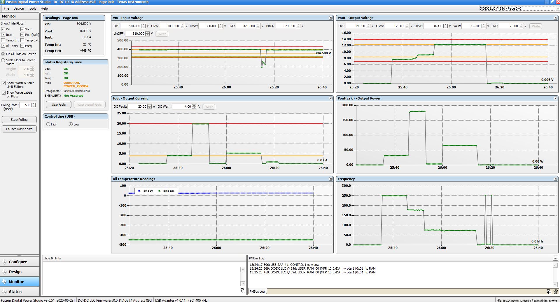
  2. During the light load operation the converter doesn’t switch to cycle skipping mode. In the original firmware on the EVAL board there were two option one was light load condition where the converter goes down into PWM mode and the pulse skipping condition where pulses comes in for certain time and then shut off. From the firmware that I got from TI website, at no load the converter stays at the 89Khz frequency while in the original code on EVAL board at no load the frequency used to jump up to 150Khz and then it starts to reduce down the pulse width (PWM mode).

Where can I find the updated code which is same as the one on EVAL board as dissipating 25W at no load (with the code available on TI website) is not feasible.

Some questions on the software side:

  1. When operating in constant current mode to say down to 20Amps the converter doesn’t stay close to the resonance frequency and starts shifting towards the higher frequency side and end up in PWM mode. Is it because of the LLC parameters used in this EVAL board design or is it the nature of the PI filter used for the constant current operation. As per the simulations, the LLC converter can operate upto 50% of the rated current value in the resonant frequency boundary.
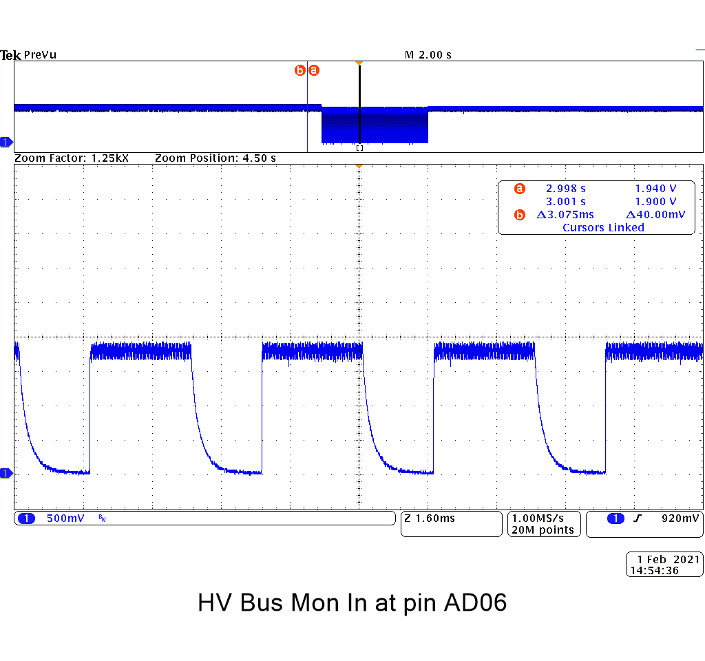
  2. There is a dead time between the DPWM0A and DPWM1A during rising edge. In the LLC design we never put any sort of delay between the rising the edges of DPWM0A and DPWM1A. It can be modified in the GUI but does this dead time has any significance?
  3. Some of the constants used in the TI firmware for LLC has ADC scales for current, voltage and temperature way off from the calculated parameters based on the resistor divider ratios showed in the schematic. Does these variations has any significance?
  4. I tried to add in additional  FILTER_PMBUS_ REGS in there for different startup coefficient of constant current loop but I couldn't locate where these variables are defined to able to define everything in same place and make it work. 

    EXTERN FILTER_PMBUS_REGS filter0_pmbus_regs;
    EXTERN FILTER_PMBUS_REGS filter0_start_up_pmbus_regs;
    EXTERN FILTER_PMBUS_REGS filter0_cp_pmbus_regs;
    EXTERN FILTER_PMBUS_REGS filter1_pmbus_regs;
    EXTERN FILTER_PMBUS_REGS *filter_destination;

    It shows they are extern variables but where are they defined?

    Hope to get an answer soon.

    Regards,

    Nitish

  • Hi Nitish,

    The firmware for this EVM should be v1.2, could you please tell me which versions of firmware you are comparing, and I will check if there is anything that will cause the behavior you are describing.

    Please tell me what input voltage you are using, as this can have an impact on the frequency as you can see from Section 0.9.3 of the LLC EVM User guide:  

    For your questions:

    1. To avoid high switching frequencies, the UCD will automatically switch from LLC to PWM mode. 

    2. If the SR FET is switched on too early, there can be reverse current. So there is some delay to avoid this condition.

    3. If you could please give me an example of a constant that you are looking to change and I can walk you through the calculation.

    4. These definitions will be device specific, so they will be in the cyclone_filter.h file in the "/device/UCD3138A/header" folder.

    Regards,

    Swami

  •  Thanks for your reply.

    I am using input voltage of 380V and the GUI reads it as 400V internally. I am using software version 1.2

    Some recent vulnerability I noticed is that the converter sometimes just turns off all of a sudden (very random) and the GUI starts reading the input voltage as 270V even though the input stays at 380V. Because of this voltage reading, the UV Vin fault kicks in and turns off the converter.

    I re-did the test for no load, the losses are 8W (not 24W) but the converter doesn't go into light load condition and stays close to resonance.

    There are two type of light load features in there, one is hardware based and the other is based on the software. The hardware one looks for the filter conditions and the software one is based on the value of output current. The software based light load enable doesn't work with the software available for download online and it turns off the converter while the one that came with EVAL board, it used to work but the output voltage hysteresis was very high. If I were to use the light load hardware feature during constant current, does it still work?

    Is it possible to add new commands on the PMBUS GUI dashboard like adjusting the slew rate of current adjustment etc.?

    1. Ok

    2. Ok

    3. I noticed the following constant value doesn't match with the scale, plus the readings of current, temperature and input high voltage doesn't match with actual readings on GUI.

    For example: adc12_vout scale : In code it is 145.21

    As per the calculations, it should be (1k*4096)/(3.3*(1k+10k+0.1k)=111.8209

    4. I couldn't locate these variable declarations

    Regards,

    Nitish

  • Hi Nitish,

    I am trying to get details of the firmware shipped with the EVM, so let me update you by Jan 26th on that.

    The GUI voltage should be reading correctly as long as there are no issues with the connections, so I am not sure why the voltage jumps down in this case. It may also likely cause some of the control variation you are seeing.

    It is not possible to add new commands to the GUI at this time unfortunately.

    For your other questions:

    3. The voltage range on the ADC is 0-2.5V, so the calculation will be  (1k*4096)/(2.5*(1k+10k+0.1k)

    4. I think I misunderstood your question here. Are you trying to change the filter parameters? For example the "filter0_start_up_pmbus_regs" are configured in configuration_functions.c. Please let me know if this is still not what you are looking for.

    Regards,

    Swami

  • Hi Swami,

    Please double check the current and Vin DC readings on the eval board, they are off by a big percentage and temp ext. reads a negative value.

    3. Thanks for the clarification on that 2.5V reference. This explains why the voltage (Vout) reading is accurate on GUI.

    4. I am trying to add additional register as filter1_start_up_pmbus_regs which will hold the value of startup coefficients for constant current loop. If the coefficients are high then the current control loop takes over really fast, avoid high overshoot but is oscillating. On the other hand if coefficients are low in value then before the current loop takes over at the startup the current goes 2-3x of the constant current limit but eventually after 50-60ms settles down to a steady value. So, in order to take advantage of both, I need to startup with the high kp and Ki coefficients in CC loop (filter1) and after startup change coefficients to low kp and Ki to keep the loop response stable. For a way around that, I change the values manually after startup instead of calling a variable filter1_start_up_pmbus_regs.

    Regards,

    Nitish

  • Hi Nitish,

    I am still checking on the default firmware in the EVM.

    For the other questions:

    4. I think what you described should already be implemented in the EVM code in the state machine in "standard_interrupt.c".

    In the function "transition_to_idle_state(void)", the filter is initialized to "filter0_start_up_pmbus_regs" and then in the function "cpcc_adjustment(void)" it switches to either "filter0_pmbus_regs" or "filter0_pmbus_regs" depending on the supply state.

    The "filter0_start_up_pmbus_regs" is initialized in "store_restore_functions.c" in the function "restore_default_all(void)" as "filter0_start_up_pmbus_regs_ptr = &filter0_start_up_pmbus_regs_constants;".

    And "filter0_start_up_pmbus_regs_constants" is initialized in "constants.c" as "volatile const FILTER_PMBUS_REGS filter0_start_up_pmbus_regs_constants = DEFAULT_FILTER_0_START_UP_PMBUS_REGS;". 

    DEFAULT_FILTER_0_START_UP_PMBUS_REGS is defined in "pmbus_topology.h"

    You may have to modify the state machine if you are trying to have two different startup coefficients.

    I will update you tomorrow on the default firmware for the EVM.

    Regards,

    Swami

  • Hi Swami,

    Thanks for the reply. I am looking to have different FILTER_1_STARTUP_PMBUS_REGS for constant current loop.

    I re-read the code and found that EXTERN variable used to 

    #ifdef MAIN // If it is the main routine
    #define EXTERN // If it isn't extern, so define it as nothing
    #else // If it isn't the main routine
    #define EXTERN extern // If it is extern
    #endif

    I see the MAIN is defined in main.c so EXTERN is null. I was confused with the following declaration:

    EXTERN FILTER_PMBUS_REGS filter0_pmbus_regs; 

    I thought the variable is defined somewhere else in the code. I will try to add the EXTERN FILTER_PMBUS_REGS filter1_pmbus_regs; in the similar way and see if I ran into some errors or not.

    Regards,

    Nitish

  • Hi Nitish,

    I am looking into the differences between the firmware shipped with the EVM vs. the version 1.2 on the web, and I do see some differences in how the burst mode is handled which could be what you are seeing, but there might be other differences. I need some more time to check all the differences, so I will get back to you by this Friday Jan 29th on this.

    Regards,

    Swami

  • Hi Swami,

    Thanks for the reply. 

    I am once again seeing the glitch in high voltage DC input.

    Probed at the AD06 where Vin Mon is connected and observed this waveform, 

    I also checked the source for difference in current readings and they are because of the hardware. For 1 amp of current it reads 41 mV instead of 35.7mV.

    Regards,

    Nitish

  • Hi Nitish,

    The Voltage waveform definitely looks unusual. I am starting to wonder if there is some hardware issue. Do you have access to another UCD3138ALLCEVM150 that you can compare? It seems like something is damaged on this one.

    I am trying to duplicate the issue with the frequency getting clamped, but I don't see the same issue at the moment. I am using the default version 1.2 firmware. Could you please tell me the changes you have made so far to the firmware?

    Regards,

    Swami

  • Hi Swami,

    I don't have additional EVM with me. This problem started happening when I modified the code, maybe something is wrong with opto-coupler. I couldn't find the schematic for the bias board to see where the opto is located for providing HV Bus info.

    I have made the following changes so far:

    1. Have different startup coefficients for current regulation loop.

    2. Enabled the ramp in FE1.

    3. Higher steady state coefficients of Kp and Ki in constant current loop.

    4. Commented out software light load control, still have hardware light load turned on. 

    5. Added additional states based on battery charging curves.

    6. Removed the code for current share and constant power.

    7. Modified some of the PMBUS commands of warning to set the pre charging current and float voltage of the battery using GUI.

    8. Added a function to re-configure Pgood and failure pin as red and green led to show different stages of battery charging.

    9. Apart from that haven't modified any of the peripheral setup registers.

    Regards.

    Nitish

  • Hi Nitish,

    The schematic for the main board should be in the user guide 

    The schematic for the control card is at 

    I would recommend going back to the original firmware, and checking first that everything is working as expected.

    Then make the modifications one at a time to see which one is causing the issue.

    I would make the modifications in the following order:

    1. Modified some of the PMBUS commands of warning to set the pre charging current and float voltage of the battery using GUI.

    2. Higher steady state coefficients of Kp and Ki in constant current loop.

    3. Have different startup coefficients for current regulation loop.

    4. Enabled the ramp in FE1. 

    5. Added additional states based on battery charging curves.

    6. Added a function to re-configure Pgood and failure pin as red and green led to show different stages of battery charging.

    7. Removed the code for current share and constant power.

    8. Commented out software light load control, still have hardware light load turned on. - I think it will be better to leave this software controlled.

    Regards,

    Swami

  • Hi Swami,

    The bias board which has this HV Bus sense is shown as PWR050 which is a different board.

    I found my mistake on why the startup register for filter 1 was not working. I had to add the following changes:

    1. Restore default function: Add the startup register 1.

    2. Add this condition : if((source == &filter1_pmbus_regs) || (source == &filter1_start_up_pmbus_regs)) instead of  if(source == &filter1_pmbus_regs)

    I think the light load condition doesn't turn on at 12V because the LLC is able to find a stable point within the resonant frequency range without making the voltage shoot up to start the light load condition. Light load pulse skipping is observed if the voltage set point is reduced down to let say 11V, then it works fine. I will try to turn off the SR drive during light load and see if it bump up the efficiency or not.

    At first when I tried the V1.2 software the power supply just turned off when I enabled the software light load condition using the PMBUS command of light load turn on. It was working fine in the original software that was there in the TI Eval board but the voltage hysteresis was very high. 

    Can you please explain on how the following values are calculated and how they work. What condition is looked at inside to get into light load condition (hardware based). From reading the code it seems they are working off of voltage filter, if I have to apply the same thing to the current filter i.e. during the condition of pre-charging when the power requirements are very low, how can I calculate these values

    LoopMuxRegs.LLENTHRESH.bit.TURN_ON_THRESH = HWBMTHRESH_REG; //ZCS feature
    LoopMuxRegs.LLDISTHRESH.bit.TURN_OFF_THRESH = HWBMTHRESH_REG; //ZCS feature
    Filter0Regs.FILTEROCLPLO.bit.OUTPUT_CLAMP_LOW = (HWBMTHRESH_REG-1000); //ZCS feature

    Regards,

    Nitish

  • Hi Nitish,

    The HWBMTHRESH_REG should be half period in 250ps multiples ~ 181.8KHz HWBM entry threshold. It does work off the voltage filter, I don't think there is a way to directly apply this in the current filter. You may have to experiment with it and see, and also it may be different from board to board, so not sure if it is that useful.

    Turning off the SR fets seems like a good idea, at least the top SR fet. Let me check if anyone else has tried this in our group and if they have any ideas. 

    Regards,

    Swami 

  • Hi Swami,

    I see what I can do with the light load thresholds and play around it.

    I turned of the SR FETs (both the FETs) at no load, the no load power consumption went from 8W down to 4W.

    Nitish

  • Hi Nitish,

    The schematic for PWR050 is located at  Hope it helps in figuring out if the board has an issue.

    I couldn't find anyone that has used the current filter to do the transition to low load. Hopefully switching off the SR Fets will work for you.

    Regards,

    Swami