This thread has been locked.

If you have a related question, please click the "Ask a related question" button in the top right corner. The newly created question will be automatically linked to this question.

TIDA-00817: Active balancing failed on EM1402EVM

Part Number: TIDA-00817

Hello.

This is the following thread of "https://e2e.ti.com/support/tools/sim-hw-system-design/f/234/t/883441"

I successfully connect between TMS570 and My host PC with bq76PL455_GUI by opening COM port. 

I have a problem while operating gui with balancing On button.

As a result, Balancing is not working.

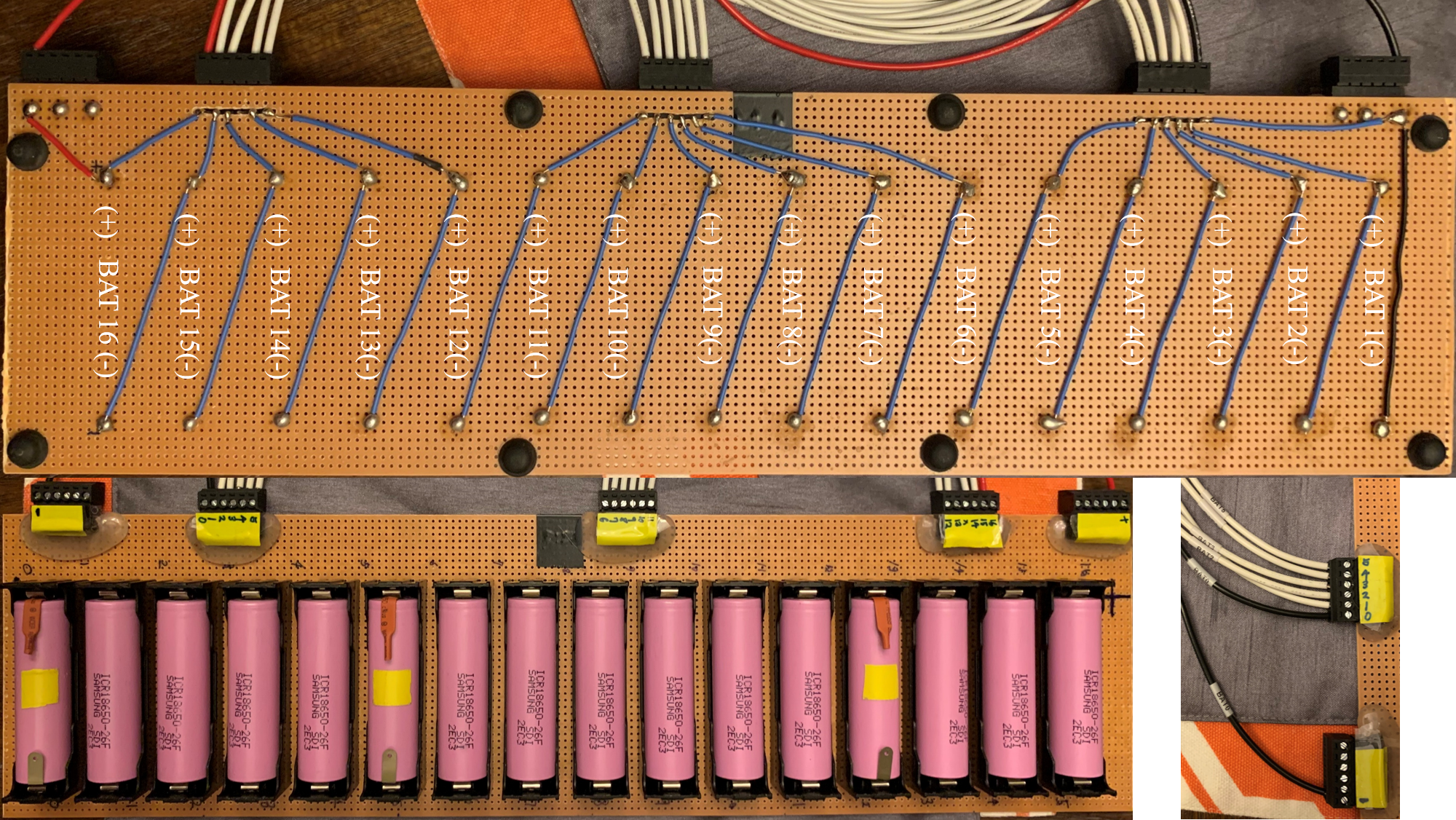
With the 16 batteries, I put 13 batteries as a normal cell which has 3.7V and 3 batteries as low SOC cell which has 3.5V

I click the Balance-on button at 25 sec. here is the result screenshot of normal cells. 

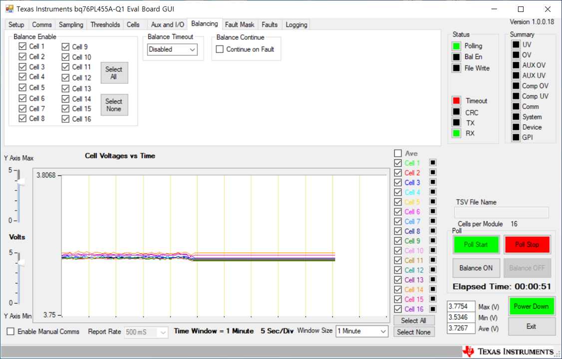
here is the result screenshot of Low SOC cells. 

Compare with the result from TIDUBI0, p16, P17, It is definitely wrong. 

For the solution, I checked the connection again. Cause I think the signal from the MCU is wrong first. 

Here is the question. 

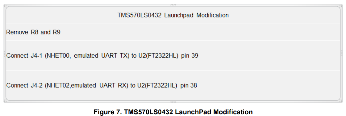
Which connection guideline should I follow for the "http://www.ti.com/lit/zip/tidcbz0" 
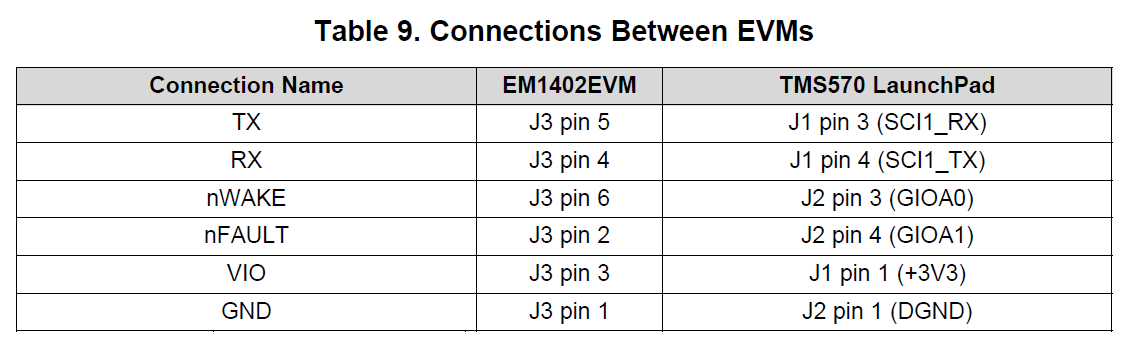
or 

  • Hello,

    Thank you for your question! A few requests to assist in debugging:

    Please use a logic analyzer to monitor the MCU RX/TX lines going to and from the balancing portion (to ensure the commands are being sent at all).

    It does appear from your images that balancing is occurring, but potentially from the wrong cells (depending on what you are setting in the GUI) and potentially the wrong current. Can you confirm if you have changed anything in the code?

    Thanks!

    Vince

  • Thank you for your reply. 

    I have used this code :  "http://www.ti.com/lit/zip/tidcbz0"

    I didn't change any codes in the code in tidcbz0. 

    After balancing on button clicked polling is stiil available. 

    But If I try to click the power down button, It shows connection failed.  

  • Hello,

    Thanks for your follow-up! Would you be able to monitor the MCU TX/RX lines to see which commands are being sent and received? This will assist in debugging if this is a connection issue, communication collision, etc.

    Thanks!

    Vince

  • Thank you for the reply. 

    Here is the waveform of the Logic analyzer

    After enter, click the Poll start : 


    with Polling start, Balance On status. 

    without clicking reset button on MCU Launchpad, It won't wok even polling. 

    Thank you. 

  • Hello,

    The fact that the polling is not working while balancing suggests that something is going wrong with either the order of commands (polling first versus balancing first), or this is a different version of the GUI. Would you be able to confirm the download location you received this GUI from (what particular page)? Could you also provide the version number?

    Thanks!

    Vince

  • Good afternoon,

    Based on the installation folder information, 1.0.0.18.

    I'm sorry I can't remember the location of the download.

    Is there any updated version for that?

    Thank you. 

  • Hello,

    The GUI you are referring to is not the correct GUI. That GUI is for the PL455 only. Please utilize the GUI included in the "Software" section of the appropriate device (TIDM-TMS570BMS):

    https://www.ti.com/tool/TIDM-TMS570BMS

    This website includes a zip file labeled "TIDM-TMS570BMS Software" which contains the correct GUI.

    Let me know if this solves your issue!

    Regards,

    Vince

  • Hello. 

    the file version you linked with reply is also 1.0.0.18. 

    And it also has same problems. 

    Any more suggestion you have, I'll appreciate.

    Thank you. 

  • Hello,

    Although the two GUI have the same version number, would you be able to try the linked GUI and see if it works? It is still possible that despite having the same version number, you still have the incorrect GUI (for the BQ76PL455A-Q1 only, and not the EM1402+BQ76PL455A-Q1 combination).

    Regards,

    Vince

  • Yes as you mentioned in the last reply, 

    I have used GUI and Code in the file you linked. 

    And it has still the same problem. 

    The balance on button clicked, Timeout in status turned red. 

    and MCU should be reset.

    Thank you. 

  • Hello,

    Thanks for checking on this, as the correct GUI is essential to proper function as well. The software doesn't seem to be the issue here, but there does seem to be a lack of communication across the SPI lines, as shown in your previous screenshots, so please double check that Figure 6. is followed for connecting the connections (which you provided in your original post).

    Next, if there is still no signal on the SPI lines, please ensure that the following modifications from Figure 7. have occurred correctly (I believe you stated previously that you did correctly make these modifications, but I just want to double check):

    If these NHET connections are not made properly, then the code may never get to the SPI portion (which may be why there is no activity).

    Finally, if Figure 6. and Figure 7. are both correctly followed, and you still don't see any data coming out of the SPI lines in your device, we may need to dig into the cell connection setup you are utilizing.

    Please let me know what you see on the logic analyzer after the above two suggestions though, as I think they may help at least begin the SPI transmission.

    Let me know what you find out from these debug steps so we can continue to assist you.

    Regards,

    Vince

  • Thank you for your help. 

    I'm double-checking the thing you recommended. 

    I'll add the result soon. 

    But one thing I want to make sure. 

    I didn't keep an eye on the build warning.

    But I realize that I got lots of warnings. 

    Could you check it is ok?

    Thank you. 

  • Hello,

    Thanks for providing this! It looks like that the only concerning issues are the "subscript out of range" warnings. Could you provide the line numbers your compiler shows for the "subscript out of range" errors?

    Also, could you let us know what compiler version are you using (found by: right-click the project in Code Composer Studio->choose properties->"General" tab->look at the dropdown with the compiler version used)?

    Looking forward to hearing the results of the previous post suggestions too!

    Thanks!

    Vince

  • Hi, 

    As the previous post suggests, I double-checked, there is no difference.  No connection problem at all. 

    For the latest post, the error came from below. 

    And the compiler version perspective, I have used the below screenshot's version. 

    I tried to use another version of the compiler which is 5.1.1 with the CCS V5, but in this case, the diode D10 is light on in red after debugging, the system cannot even enter the GUI. 

    Below is the 'GENERAL'  tab's screenshot for the CCS v5. 

    Thank you.

  • Hello,

    Thanks for the screenshots! It looks like the "subscript out of range" issue is actually fine, every single "WriteReg" call in the project uses 4 or less bytes, so those parts of the case statement will never be reached, and so it will never go out of range.

    The compiler version you are using should be fine too, so I would be surprised if that was the issue. Just in case though, let's try installing the closest compiler version to the original:

    Help->"Install Code Generation Compiler Tools..."->Search for ARM Compiler Tools Version 5.0.11

    This is the closest compiler available version to the desired 5.0.4.

    Again, considering everything else looks good, I am very surprised we are still not seeing correct behavior from the code and hardware, thank you again for your patience as we work together to debug this.

    Regards,

    Vince

  • Hello 

    As you recommended, I installed the CCS 5.4.0 so that I can use the compiler version 5.0.4 exactly. 

    With that compiler version, I got the same problem. 

    Still, after balance On button clicked, the 'Timeout' tab turns into red light, all the GUI is frozen unless I reset the MCU.

    Thank you. 

  • Hello,

    Thanks for trying this. I think the only possibility for the device to still be nonfunctional after starting balancing (assuming all of the previous requests are 100% correct) is an incorrect connection or POR event happening on the EM1402EVM. Can you scope plot the power rails of PL455 and EM1402 when you attempt to start balancing? It almost seems like the PL455 is being DRST by a power surge of some kind.

    Can you also ensure that the batteries are in series (not all in parallel)?

    Thanks,
    Vince

  • Hi, 

    Thank you for your help. 

    1. Cause we are in the stay in home order, I can't reach the laboratory to get an oscilloscope.

    Is there any way I can measure the power line with a logic analyzer? 

    2. Yes, I connected the battery as a followed picture. 

    3. I think I have no idea which part should I fix more with this. 

    If I send this hardware to the Ti, could you test with this? Totally 2 months is delayed with this hardware debugging problem. 

    But even so, I still want to fix this problem and want to know where is the problem. 

    I was wondering If you can help me with this. 

    Thank you. 

  • Hi Kim, 

    Yeah, I understand is difficult to work in the lab with the current situation. Unfortunately we cannot test your hardware. You'll need to check the specification document for your logic analyzer and check the voltage rating to make sure you don't exceed it. Since it is used for digital signals, it more than likely won't tolerate signals above 5V logic level, but you'll need to check the spec.

    Regards,

    Leslie

  • Hi Kim, 

    I'm going to close this thread since we haven't heard back from you. Please create a new thread if you need further assistance once you get lab access. 

    Regards,

    Leslie