This thread has been locked.

If you have a related question, please click the "Ask a related question" button in the top right corner. The newly created question will be automatically linked to this question.

TIDA-01606: LEM Current sensor issue

Part Number: TIDA-01606
Other Parts Discussed in Thread: OPA4340,

Hi Manish,

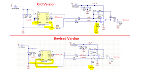
As you mentioned in the design guide, the LEM senor phase A has a noise issue. However, I noticed that the LEM sensor Phase B also has the same problem. I noticed that in the new schematic revision, the LEM sensors have been modified. I am wondering if the modification has solved the noise issue of the LEM sensor Phase A and B. If not, do you have any suggestion how to solve the noise issue of the sensors by applying filters in specific locations?

Regards,

Jalal

  • Hey Jalal,

    I am looking into your question and will respond shortly.

    Best,

    Peter

  • Hey Jalal,

    On page 28 of revision D, it mentions that OPA4340 is used because it has lower BW and thus will attenuate noise from the long input traces.

    I can’t find the schematic snippets you sent and they are pretty blurry, but from what I can infer the old schematic is using a ground referenced signal chain, while the new one has a bias (or reference) voltage and this amplifier is gaining up a differential signal. The latter scenario will always be better in terms of operating amplifiers within linear region and rejecting common mode noise.

    I’m sorry but I cannot find more information about the noise, but you can always reduce noise by placing low pass filter capacitors and also feedback capacitors on the amplifier to reduce bandwidth and increase attenuation of higher frequency noise.

    Hope this helps.

    Best,

    Peter

  • Thank you peter. I tried the new sensor circuit but still there is a noise issue. Also, I reduced the OPAMP bandwidth, but the noise issue persists.

    I would be grateful if one of the application engineers involved in the project also gives me some suggestions.

    Regards,

    Jalal

  • Hey Jalal,

    The noise pickup from phase A is a problem with the CASR-15 flux gate device, which I am not an expert in; however, it is possible that due to the layout of channel A's current path, the CASR device (U3) is picking up stray magnetic fields causing noise pickup. Thus, this is why this channel A information (sensed by U3) is not used in the control loop.

    I would advise noting the differences in layout (around the CASR devices, U3,U4,U6) between channel A and the other two channels to see where the noise pickup could be coming from. I don't think this noise issue has anything to do with the biasing of the device with the reference voltage as you show in your first image. If this was the root cause, then U3 would not still be having this issue.

    Sincerely,

    Peter

  • Hi Peter,

    Thank you for the advice. I am running a hysteresis controller, and the converter-side inductor current should be sampled at high frequency. I did the high-frequency sampling rate at 1MHz by using LEM sensors. However, due to the problem of the LEM sensors, I decided to use grid-side current sensors which are SDFM. But, the point is that the maximum sampling rate I can achieve with SDFM is 75 kHz. I am wondering if it is possible to reach a higher sampling rate by SDFM.

    Thanks,

    Jalal

  • Hey Jalal,

    There certainly are other ways/devices that can be used to get 1MHz sampling at grid-side current. Here are other isolated ADCs we offer (sorted by fastest sampling rate):

    https://www.ti.com/isolation/isolated-adcs/products.html#sort=p157max;desc

    Here is an overview of all isolated devices (ADCs, amplifiers, digital isolators, etc.):

    https://www.ti.com/isolation/overview.html

    It is all dependent upon your system requirements for error, speed, cost, isolation level, etc. Maybe it might be easier/better to use an isolated amplifier driving a ground-level ADC with 1MHz sampling, or maybe floating a regular ADC and then isolating the digital bus lines from the floating ADC to a down stream, ground-level microprocessor. 

    Going back to the original issue, the noise on the LEM sensor, channel A can only be due to layout and proximity of the signal chain traces to noisy electro-magnetic fields. The board made for TIDA-01606 is not perfect and was made for demonstration purposes, not a final product. Channel A traces potentially need to be revised and/or shielded to prevent noise pickup.

    Sincerely,

    Peter