This thread has been locked.

If you have a related question, please click the "Ask a related question" button in the top right corner. The newly created question will be automatically linked to this question.

Firmware problem

Other Parts Discussed in Thread: TPS65981

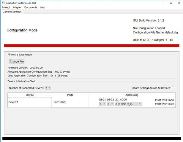
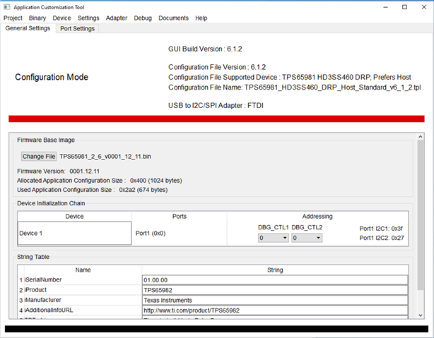
After loaded the bin file to  EEPROM. I am getting this one.

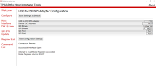
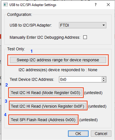
But It should show APP in Mode return register..

Can you help me out ? How I can reach there?

Thanks.

Rajat

  • Hello,

    Which PD controller are you using? could you try with the latest GUI? 

    Thanks
    Prajith

  • I am using TPS65981 controller. I am using v0.12.3. do you have an idea ?

  • The latest version of the GUI for this product is v6.1.2. You can download this version from TI.com here:

    https://www.ti.com/tool/TPS6598X-CONFIG

    Give it a shot with this version of the tool and let us know if you're still seeing issues.

  • This version is using. can you tell me how to configure ''BOOT'' mode to ''APP'' mode ??

    I am waiting.

    regards,

    Rajat 

  • There's not a configuration setting that changes from BOOT mode to APP mode. The PD controller boots up in BOOT mode always, then reads in the Application Configuration code, and if the Application Configuration code was valid, the controller then switches into APP mode. There are a variety of issues that can cause the PD controller to reject a binary. It could be that the binary was corrupted, that EEPROM flashing failed, that invalid configuration settings were used, or that the PD controller is unable to read from the EEPROM. 

    The reason we're asking that you upgrade to the latest version of the GUI is so that we can support you better and help to debug the issue. The version of the tool you're using is 6 years old and we've made a great number of improvements and enhancements since then that provide additional information that can help us debug the problem.

    The newer version of the tool provides 'templates' for each device. The first step to debugging the issue is to use the default template provided in the tool to flash the device. If that succeeds and the device boots into APP mode, then we know the hardware is good and we know the issue is with the Application Configuration settings being used. If using the default template for flashing still has the device booting into BOOT mode, then we can take a look at your hardware setup. 

  • Thank you for your text. Can you give me the link where I can download the latest version of this tools. I used this links for the tools.

    https://www.ti.com/tool/TPS6598X-CONFIG

    Here, I have attach my schematic. Could you check it ?

    Pin 22 (USBC_BUSPOWERZ ) connected to Pin 51 (USBC_LDO_3V3) Because I am not using any external power to get the power to my board.

    Can you check the hardware setup ?

    I am using default .bin file. (TPS65981_2_6_v0001_12_11.bin)

    this .bin file is the right one ? 

    Thanks.

    regards,

    Rajat

  • Can you tell me where can I get the valid application code?

  • The unique I2C address is based on the DEBUG_CTLX pins, and resistor configuration on the
    I2C_ADDR pin.

    I could not find any pin I2C_ADDR pin in TPS65981 chip. Can you tell me about it ? and hoy I set it  in Hardware ?

    I connected DEBUG_CTL1 (Pin 45) and DEBUG_CTL2 (Pin 44) pins connected to GND. Slave I2C address is x27. 

  • Rajat,

    Try out this process so we can establish a baseline and let me know the results:

    1. Launch the Application Customization Tool v6.1.2
    2. Go to Project -> New Project
    3. Select the TPS65981 device
    4. Select the Standard template option
    5. Select your desired port type option.
    6. Once complete the GUI will load the default template, preconfigured for the TPS65981.
    7. Go to Binary -> Flash from current project
    8. Change your USB Adapter to FTDI and then click OK to flash the device
    9. Unpower and reboot the device
    10. Once flashing and rebooting is complete you can check the status of the device by going to Adapter -> Configure I2C/SPI Adapter Settings
    11. Sweep the I2C address range to discover the device. Then test the Mode, Version, and Read registers to verify everything is working correctly. You should now be in APP mode and see that displayed in the Mode Register (0x03)
  • Hi Rajat,

    I2C address is based on DEBUG_CTLx and you're right the design gives the address of 0x27.

    If VIn3V3 is present that you should be able to boot to APP mode.

    You can monitor your SPI traces and make sure there are activities when power is first provided.

    Regards.

  • Hi,

    I want to use my USBC Connector as a power delivery (Profile 2 )  (12V/1.5A and 5V/2A) and as well as data transmission. How I will set the parameters from the tools (Application Customization tools) and create .bin file. Can you explain me step by step??

    Thanks.

    regards.

    Rajat Barmon