This thread has been locked.

If you have a related question, please click the "Ask a related question" button in the top right corner. The newly created question will be automatically linked to this question.

TIDA-010080: Can design be easily modified to perform constant current battery charging?

Part Number: TIDA-010080
Other Parts Discussed in Thread: PMP40766, , TIDA-010081, TIDA-010015, UCC256301, UCC256403

1) Can TIDA-010080 (500W, 48V AC/DC ref design) provide CC output?  If not, can it be made to provide CC output by simply replicating the CC control design as in PMP40766 reference design?

2) TIDA-010080 design guide section 2.4.1.2 states that the PFC stage de-rates to 300W at low line inputs (90-127Vac).  My understanding is that this means that PFC stage will limit power output to 300W at low line inputs.
However, the efficiency curve for 115Vac input goes out to 500W, showing ~92% efficiency between 300W to 500W output.
I am unclear on how the efficiency curve shows 92% efficiency at 500W when the PFC stage doesn't put out more than 300W at 115Vac input.

3) I have a similar question as (1) on TIDA-010015 (500W, 24V AC/DC ref design) and TIDA-010081 (1kW, 54V AC/DC ref design).
In both TIDA-010080 and TIDA-010081, the sensed current is processed and fed back to the BLK pin of the half-bridge LLC controller UCC256301, while in TIDA-010015 it is fed into the LL/SS pin of the same half-bridge LLC controller UCC256301.

3a) I am trying to understand what the above two feedback mechanisms are accomplishing.

3b) Can TIDA-010015 and TIDA-010081designs be easily modified to perform constant current battery charging?

I would appreciate your help.

Regards,

Nitish

  • Hi Nitish,

    TIDA-010080 is not for battery charging application, but the system can be modified to CC control as PMP40766 shown. which is quite similar.

    for the derating at low AC line , this is purely due to thermal as heatsink design is not fully sized for the heat dissipation, we recommend to increase the size of heatsink in your production design.

    for accurate secondary side OCP and OVP, we will use an opto-coupler to transit secondary side fault signal to BLK pin. this is what we done for secondary protection.

    for battery charger, we may propose PMP40766 as this is dedicated for this application.

    BR

    Max

  • Hi Max,

    Thank you for your response.  I had a couple more questions about TIDA-010080 and CC control in PMP40766:


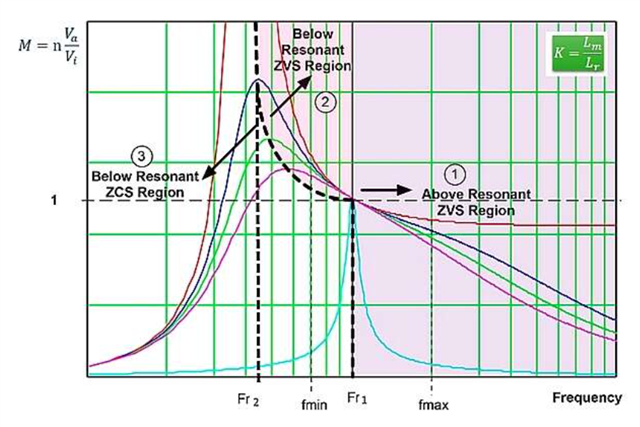
    a) The design note section 2.3.2 says "Ensure that the LLC converter does not enter capacitive (ZCS) region during the low input voltage condition; otherwise, it could make damage to the system."

    Would you mind clarifying what steps need to be taken by the system designer to ensure that LLC tank doesn't enter capacitive region?

    b)  What is the minimum output current that may be sourced by the converter when employing CC control as described in PMP40766?

    Kind regards,
    Nitish

  • Hi Nitish,

    basically, the so called capacitive region is the current in resonant tank ahead of SW node voltage, which will cause current commutation issue of Half bridge switch, so we should try to avoid this by proper design resonant circuit, firstly define the Vinmin, Vout Max and Ioutmax which is the worst condition for capacitive mode, then fine tune LLC gain to avoid the this situation, meanwhile our UCC256403 features a capacitive mode protection which will save the primary switch in case of capacitive mode operation happen

    for PMP40766, you may approach to the right person for his comment.