This thread has been locked.

If you have a related question, please click the "Ask a related question" button in the top right corner. The newly created question will be automatically linked to this question.

TIDA-00643: DRV8305 Motor control stops on stalling the motor

Part Number: TIDA-00643
Other Parts Discussed in Thread: DRV8305, MOTORWARE

Hello

I am using lab5b for speed control at increasing levels of max current limit. 

When the max current limit is kept beyond 15A(20A - 25A), the control is getting rolled over after a certain stall is applied on the motor.

I have changed the USER_IQ_FULL_SCALE_CURRENT_A and USER_ADC_FULL_SCALE_CURRENT_A to 82.5A and 165A respectively owing to sense resistor of 2mohm.

Are there any variables that need to be adjusted so that the control doesn't get rolled over(the motor control stops when stall is applied on the motor).

P.S i have tested Lab5a on the board and the same issue happened at 23A for 7mohm sense resistor. So, I changed the USER_IQ_FULL_SCALE_CURRENT_A and USER_ADC_FULL_SCALE_CURRENT_A to 82.5A and 165A for 2mohm sense resistor and then, it worked. There was no stopping of motor control.

But now, even after changing those parameters, the problem still remains and is happening at 15A itself.

I have already used lab2c for user parameter identification and it worked correctly.

Please Help.

Thanks.

  • Hi Natsu,

    I will forward to the C2000 team to help.

    I believe the higher shunt resistor value (7mohm) will cause problems because the minimum gain setting is 10V/V, and a current of 23A will results in a minimum voltage delta of 23*0.007*10 = 1.61V, which is near the saturation limit of the ADC (+/-1.65V) if VREF = 3.3V and k = 2. Any currents of 23A or higher is likely saturating and giving incorrect current outputs when using the higher shunt value. 

    Can you confirm VREF, k, and the GAIN setting used?

    Thanks,
    Aaron

  • Do you change the VDS level of DRV8305 for increasing the over current protection value? You might try to add the codes as below after HAL_setupDrvSpi() in the lab main file.

      HAL_setupDrvSpi(halHandle,&gDrvSpi8305Vars);

      gDrvSpi8305Vars.Ctrl_Reg_0C.VDS_LEVEL = VDS_Level_1p679_V;
      gDrvSpi8305Vars.WriteCmd = 1;

  • Hello Aaron

    VREF is 3.3v, 

    k is 1.

    GAIN setting is 10V/V.

    We are expecting a current of 82.5A with 0.002 shunt resistor. So, 82.5 * 0.002 * 10 = 1.65V. So, getting current until at least 50A shouldn't be a problem right?

    Although I could see 44.4A current while stalling using lab5a(current control). I cannot see the same result with lab5b(speed control).

    Thanks,

    Natsu

  • Hello Yanming

    Yes i changed the VDS Level from 0.060V to 1.679V but there is no change in the behavior. The motor is still getting stopped as soon as the input current exceeds 10A. when stall is applied on it. The test is made low speed of 200 rpm

     Iq_A = 30.4366 and Id_A = -0.27146 are the readings when the motor is getting stopped and the program is getting reset(Flag_enablesystem and Flag_enableIdentity becoming zero)

    Thanks,

    Natsu

  • Tried changing the value of k to 2.

    Still the same error.

  • Any happens if you run the motor at a higher speed or with a light load? Please check if the hardware board or the motor can support such high load or current.

    You might try to use the kits supporting in the MotorWare or MotorControlSDK.

  • Hello Yanming

    As soon as the RPM is increased, the board was able to draw more current(33A at 10000RPM) while stalling . But, the motor is getting stopped at lower RPM.

    If the issue is really with the hardware board, then there should also be an issue with lab5a also right?(current control). We have just changed the sense resistor from 7mohm to 2mohm and updated the USER_ADC_FULL_SCALE_CURRENT and USER_IQ_FULL_SCALE_CURRENT to 165 and 82.5 respectively.

    Please tell me what all parameters needs to be monitored for increasing the input draw current.

    Can you please explain the difference between Id_A, Iq_A, Is_A and how they are related to the input current?

    Thanks

    Natsu

  • What's the rated speed of the motor? And what low speed did you run the motor? Please be note that 200rpm is tool low for your motor to run with a heavy load. You might have to try sensored-foc if you want to run this motor at low speed with full load.

  • The rated speed of the motor is 131A. 

    The motor was tested at 200RPM and getting stopped when stalled.

  • The rated speed of the motor is 131A. 

    What's the rated and maximum speed of this motor?

    What load is adding to the motor when it runs at 200rpm? As mentioned above, the 200rpm is too low for your motor to run with sensorless-FOC at full load.

  • Hello Yanming

    Unfortunately , I cannot provide you any information regarding the load.

    Regarding section 14.1.1.4, is it possible that the tuned kp and ki values play a significant role in stopping the motor at low speeds while applying torque

  • Hello Yanming

    The rated speed of the motor is 974 RPM and maximum speed is 15589 RPM.

    I have increased the speed to maximum and then applied torque on it for which it is functioning.

    Now, the torque test has been done such that the motor load has been fixed and not made to move. At this position, the motor should draw maximum current but it is not able to do so.

    Instead the controller is getting rolled over.

    Thanks

  • Could you please share any more test waveform and information to show the questions you mentioned above and how did you test the motor? Yes, you need to tune the Kp and Ki of the speed PI controller, and have to use different Kp and Ki for low speed and high speed according to your motor and system.

  • Hello Yanming

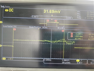
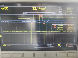
    Above are the images of MCU_ISEN_A 

    Left image is when USER_MOTOR_MAX_CURRENT is 40A.

    Right image is when USER_MOTOR_MAX_CURRENT is 10A.

    There are lot of distortions when max current limit set is 40A which amounts to noise in the signal.

    Can it be solved by modifying the current sense RC section or by modifying the speed of ADC sampling?

    I have tried tuning the Spd Kp and Ki values but of no use.

    The motor is tested with a torque testing unit where the load is fixed when the motor is made to rotate thus trying to draw maximum current from the start.

    Thank you

  • If you have try to tune the speed PI controller, but it can't improve the performance as you want. You have to use the sensored-FOC for running the motor at low speed with a heavy load if possible.

  • Hello Yanming

    Thank you for your suggestion.

    Can you please elaborate what is Vsnsocp_trip(phase short protection limit) which is given as 2V in DRV8305 datasheet.

    The ADC value which is attached in the photos above are given a maximum of 1.65V for both USER_MOTOR_MAX_CURRENT 10A and 40A. How should the ADC value be interpreted as it is supposed to rise according to the current drawn?

    How is current sense section RC filter subjected to R=56ohms and C=2200pF? I have tried changing the values but the motor doesn't rotate properly. Please elaborate how these values can be set

    Thanks

  • The ADC value which is attached in the photos above are given a maximum of 1.65V for both USER_MOTOR_MAX_CURRENT 10A and 40A. How should the ADC value be interpreted as it is supposed to rise according to the current drawn?

    You might take a look at the datasheet of the DRV8305, and set the right value of the control registers for the DRV8305 according to your motor.

    How is current sense section RC filter subjected to R=56ohms and C=2200pF? I have tried changing the values but the motor doesn't rotate properly. Please elaborate how these values can be set

    You might keep the original value on the board, it's better to use a 50~100 (OHM) resistor, and (1nF~2.2nF) capacitor for the RC filter, and make is cut off frequency is far higher than the PWM/Sampling frequency.