This thread has been locked.

If you have a related question, please click the "Ask a related question" button in the top right corner. The newly created question will be automatically linked to this question.

TIDA-00381: How does the phase shift work

Part Number: TIDA-00381
Other Parts Discussed in Thread: TIDA-00318, UCD3138, UCD3138A

Hi,

TIDA-00381 is very similar to what we plan to do.The key overview of TIDA-00381 is as follows:

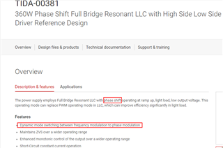
That's what I care about most.

So I downloaded the firmware of TiDA-00381 and read the source code.

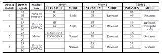
DPWM2 is configured as the primary driver and as the synchronization master,DPWM0 is configured as the primary driver and as the synchronization slave.

But the output of Filter is not used to phase DPWM0 with respect to DPWM2 at any time.(Dpwm0Regs.DPWMCTRL0.bit.MASTER_SYNC_CNTL_SEL= 0)

So my question is:

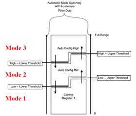
1、How does DPWM0 phase shift relative to DPWM2 when  ramp up, light load, low output voltage?

2、How does synchronous rectification(DPWM1) work when ramp up, light load, low output voltage?

3、Is there a design document for TIDA-00318?

  • The LLC with phase shift modulation uses 3 levels of automatic mode switching. The mode sequence is:
    - Mode 1: Light load and/or high input voltage - phase shift modulation for the primary switches, multi-mode for the synchronous rectifiers
    - Mode 2: Medium load - frequency modulation for both the primary and secondary switches
    - Mode 3: High output current/low input voltage - All switches operate with frequency modulation, however the synchronous rectifier pulse width is clamped to a maximum
    value based selected by the user. The mode switching between the three modes involves both the change of the modulation method and the Intra-Mux. The table below is a summary of the settings used for each mode:

    For details about multi-mode, resonant mode, and normal mode, please refer to UCD3138 programmer’s manual.

    In Mode 1, the Intra-Mux and PWM mode are configured in DPWMCTRL0 registers;
    In Mode 2, the Intra-Mux and PWM mode are configured in DPWMAUTOMID registers;
    In Mode 3, the Intra-Mux and PWM mode are configured in DPWMAUTOMAX registers.
    The mode switching boundaries are set by the mode switching thresholds shown in the figure.

  • Have you checked to see the values in the DPWMAutoMid and DPWMAutoMax registers?  That is where the magic happens for the phase mode.  Note that many of the values in DPWMCTRL0 are affected in that register.  The phase shift is not actually done using the MASTER_SYNC_CNTL_SEL bit, since that is not available in all UCDs.  Instead it is done using edge generation and intramux.  A similar technique is used in the phase shifted full bridge code.  

  • Thank you and Bliss for your reply.I checked the configuration of the DPWMAutoMid and DPWMAutoMax registers.I also understand how automatic mode switching works.

    I previously completed the same LLC project using C2000 280049.The configuration of PWM in phase shift mode is very simple.Just write the compensator output (Filter out)to the phase shift register.

    I thought UCD3138 worked the same way, obviously I was wrong.It's so complicated that I'll have to spend some time learning about it .

    Please help me confirm whether UCD3138A can realize the phase shift working mode of LLC through MASTER_SYNC_CNTL_SEL = 1 .

    Thank you.

  • It's recommended to use edge generation and intramux.