This thread has been locked.

If you have a related question, please click the "Ask a related question" button in the top right corner. The newly created question will be automatically linked to this question.

TIDA-00777: TIDA-00777

Part Number: TIDA-00777
Other Parts Discussed in Thread: TIDA-01063

Hello there,

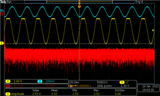
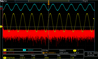
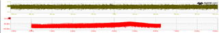
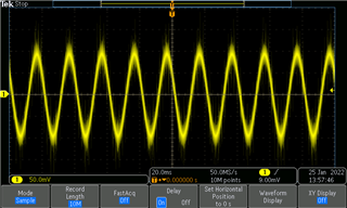
I using the exact TIDA-00777 reference design in real-time for the current measurement, but there is a huge noise in the output of the integrator ( photo attached to this msg, Yellow-output|| Orgage is the FFT of the output)

Could you please share your results if the output is noisy as well?

  • Hi, happy to help.

    I've uploaded 2 oscilloscope images from J1 and J4 for the precision measurement and fast settling paths. In both images, the blue trace (channel 2) is the input to the TIDA-00777 PCB from a function generator set to a 0.1V amplitude, 50 Hz sine wave and the yellow trace (channel 1) is the output. I also turned on the FFT math function of my oscilloscope as well. Note that the precision measurement output is clipped due to the default gain and DC offset of the TIDA-00777 design.

    Do you have a function generator to use as an input to the circuit to start debugging where your noise is coming from? Can you probe multiple points along the signal path to see if the noise is coming from a specific amplifier stage? Can you share your schematic that you've implemented?

    Precision measurement:

    Fast settling:

    Best regards,

    Ben Uhing

    Systems Engineer

    Texas Instruments Incorporated

    SEM – Grid Infrastructure

  • Thank you for the response ben.

    Can you share your schematic that you've implemented?

    I have used the exact same circuit designed in TIDA-00777 

    Changes Done:- The supply for - OPA2188AID is 3.3V

    Here is the Schematic

    Can you probe multiple points along the signal path to see if the noise is coming from a specific amplifier stage?

    Sure, below are the photos of the waveform at different stages.

    1. Waveform of the function generator at J2

    2. Waveform at test point 2

    3. Waveform at test point 1

    The RAW Rogokswhi coil output waveform attached 

    1. Current measuring - 12A (RMS)

    2. Frequency of measurement - 50Hz

  • If Possible can also RAW Rogokswhi coil output waveform at 50Hz or other frequency, current measurement? 

    Thank you,

    Virinchi

  • Virinchi,

    I went to take the measurements of the Rogowski coil today and remembered something relevant to your issue. Due to the low output power of a Rogowski coil, the TIDA-00777 will not work with any additional load on the output of the coil. Even the high impedance probes of an oscilloscope will contribute enough load to the coil output to significantly reduce the SNR output of the coil.

    I confirmed that with no oscilloscope probe on the output of the Rogowski coil, the output of the TIDA-00777 was clean like my previous image, and that adding an oscilloscope probe to the input of TIDA-00777 where the Rogowski coil was connected causes a similar noise level to yours.

    Can you try removing all load (including scope probes) from the output of the Rogowski coil other than the TIDA-00777 input and see if that solves your noise problem?

    Regards,

    Ben

  • Thanks for the reply Ben,

    Yes, The previous photo (first one) is the output of TIDA-00777, I had a damping resistor of 100 Ohms(to the output of the coil), Now I have removed it. Here are the photos/data of the output of TIDA-00777 without connecting any load (even oscilloscope) to the coil.

    1. Frequency - 100Hz, Current - 22A (RMS)

    2.Frequency - 200Hz, Current - 24A (RMS)

    3.Frequency - 300Hz, Current - 24A (RMS)

    I have a few questions below:

    1. Can you share the output of the TIDA-00777 with the coil in the input?

    2. Have you connected the earth coil? or any shielding?


    3. Can you share the photo of the setup (I mean a photo of the placement/orientation of the coil during the measurement)?

  • Virinchi,

    Please see the attached images of the output of the TIDA-00777 using the PA3209NL Rogowski coil with 10A of current as well as a picture of the test set-up.

    Could you share a picture of your set-up to see if I can help identify any sources of noise? 

    How do you have your oscilloscope set-up? Are you on peak-detect mode? Are you able to try sampling the output of the TIDA-00777 with an ADC? In the TIDA-01063 reference design, the error rate mentioned is after the output of the integrator stage is sampled by the ADS13131E08 delta-sigma ADC. I'm wondering if you're seeing more noise on your oscilloscope than would be picked up by an ADC.

    Regards,

    Ben

  • Actually, I'm measuring  TIDA-00777 using the PCB Rogowski coil (TIDA-01063-E1).

    I'm measuring with the following parameters on my Lecory oscilloscope.

  • Hi, Ben

    any solution for the above problem?

  • Virinchi,

    Do you have the ability to use a different Rogowski coil just for debugging purposes? I think the issue may stem from the voltage output swing you're getting from your PCB Rogowski coil. From the TIDA-00777, the lowest input voltage for that integrator circuit is 231.5 uV (0.5A with the PA3209NL). If you're inputting a lower voltage swing than that, and if your PCB Rogowski coil is noisier than a dedicated physical Rogowski coil, that would explain much of your noise.

    Regards,

    Ben